Isuzu N-Series. Manual - part 417


  Index      Isuzu     Isuzu N-Series - service repair manual


Search            


Content   ..  415  416  417  418   ..


Isuzu N-Series. Manual - part 417


6E-4 EMISSION AND ELECTRICAL DIAGNOSIS

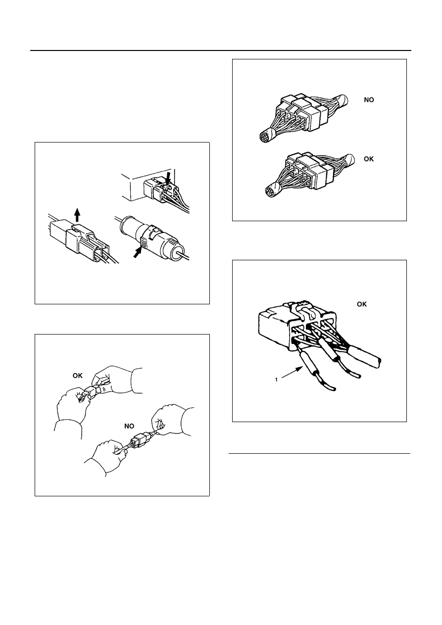
Some tang locks are released by pulling them towards
you.
Other tang locks are released by pressing them forward.
Determine which type of tang lock is on the connector
being handled.
Firmly grasp both sides (male and female) of the con-
nector.
Release the tang lock and carefully pull the two halves
of the connector apart.

Never pull on the wires to separate the connectors. This
will result in wire breakage.

Connecting the Connector
Firmly grasp both sides (male and female) of the con-
nector. Be sure that the connector pins and pin holes
match. Be sure that both sides of the connector are
aligned with each other. Firmly but carefully push the
two sides of the connector together until a distinct click
is heard.

Connector Inspection
Use a circuit tester to check the connector for continuity.
Insert the test probes from the connector wire side.

Never insert the circuit tester test probes into the con-
nector open end to test the continuity. Broken or open
connector terminals will result.

N6A1106E

N6A1107E

Legend

1. Test probe

N6A1108E

N6A1109E

EMISSION AND ELECTRICAL DIAGNOSIS 6E-5

Waterproof Connector Inspection
It is not possible to insert the test probes into the con-
nector wire side of a waterproof connector. 
Use one side of a connector (1) with its wires cut to
make the test. Connect the test connector (2) to the con-
nector to be tested. Connect the test probes to the cut
wires to check the connector continuity.

Connector Pin Removal
Connector Housing Tang Lock Type

1. Insert a slender shaft into the connector housing

open end.

2. Push the tang lock up (in the direction of the arrow

in the illustration). Pull the wire with pin free from
the wire side of the connector.

Pin Tang Lock Type

1. Insert a slender shaft into the Connector housing

open end.

2. Push the tang lock flat (toward the wire side of the

connector). Pull the wire with pin free from the wire
side of the connector.

Legend

1. Test probe

Legend

1. Connector
2. Test connector
3. Test probe

N6A1110E

N6A1111E

Legend

1. Slender shaft
2. Housing open pad
3. Pin
4. Tang lock
5. Wire

N6A1112E

N6A1113E

6E-6 EMISSION AND ELECTRICAL DIAGNOSIS

Connector Pin Insertion

1. Check that the tang lock is fully up.
2. Insert the pin from the connector wire side.

Push the pin in until the tang lock closes firmly.

3. Gently pull on the wires to make sure that the con-

nector pin is firmly set in place.

Parts Handling
Be careful when handling electrical parts. They should
not be dropped or thrown, because short circuit or other
damage may result.

Cable Harness
When installing the parts, be careful not to pinch or
wedge the wiring harness.
All electrical connections must be kept clean and tight.

Splicing Wire

1. Open the Harness

If the harness is taped, remove the tape. To avoid
wire insulation damage, use a sewing “seam rip-
per” (available from sewing supply stores) to cut
open the harness.
If the harness has a block plastic conduit, simply
pull out the desired wire.

2. Cut the wire

Begin by cutting as little wire off the harness as
possible. You may need the extra length of wire lat-
er if you decide to cut more wire off to change the
location of a splice. You may have to adjust splice
locations to make certain that each splice is at least
1.5 in (40 mm) away from other splices, harness
branches, or connectors.

3. Strip the insulation

Legend

1. Slender shaft
2. Housing open pad
3. Pin
4. Tang lock
5. Wire

Legend

1. Tang lock
2. Pin
3. Wire

N6A1114E

N6A1115E

N6A1116E

EMISSION AND ELECTRICAL DIAGNOSIS 6E-7

When replacing a wire, use a wire of the same size
as the original wire. Check the stripped wire for
nicks or cut stands. If the wire is damaged, repeat
the procedure on a new section of wire. The two
stripped wire ends should be equal in length.

4. Crimp the Wires

Select the proper clip to secure the splice. To de-
termine the proper clip size for the wire being
spliced, follow the directions included with your
clips. Select the correct anvil on the crimper. (On
most crimpers your choice is limited to either a
small or large anvil.) Overlap the two stripped wire
ends and hold them between your thumb and fore-
finger. Then, center the splice clip under the
stripped wires and hold it in place.

• Open the crimping tool to its full width and rest

one handle on a firm flat surface.

• Center the back of the splice clip on the proper

anvil and close the crimping tool to the point
where the back of the splice clip touches the
wings of the clip.

• Make sure that the clip and wires are still in the

correct position. then, apply steady pressure
until the crimping tool closes.

Before crimping the ends of the clip, be sure that:

• The wires extend beyond the clip in each direc-

tion.

• No stands of wire are cut loose, and 
• No insulation is caught under the clip.

Crimp the splice again, once on each end. Do not
let the crimping tool extend beyond the edge of the
clip or you may damage or nick the wires.

Legend

1. Over lap bare wires
2. Splice clip

N6A1117E

Legend

1. Wings of clip touching former
2. Back of clip centered on anvil

Legend

1. Splice clip
2. Align tool with edge of clip to crimp ends of 

splice

N6A1118E

N6A1119E


Content   ..  415  416  417  418   ..