Isuzu N-Series. Manual - part 372


  Index      Isuzu     Isuzu N-Series - service repair manual


Search            


Content   ..  370  371  372  373   ..


Isuzu N-Series. Manual - part 372


6A3-140 ENGINE (4HF1 / 4HF1-2 / 4HE1-TC / 4HG1 / 4HG1-T)

35. Fan Belt Adjust Plate

Install the adjust plate and temporarily tighten the
adjust plate bolt.

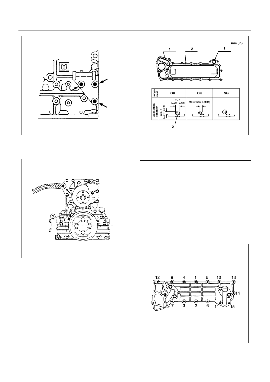
36. Oil Cooler Assembly

1) Apply 2 — 3 mm (0.08 — 0.12 in) bead of the

recommended liquid gasket (Three Bond
1207C) or its equivalent on the oil cooler fitting
surface.

2) Apply a coat of engine oil to the O-rings (2 piec-

es) and install the O-rings to the oil cooler.

Notice:
Take care that the O-ring does not get smeared with liq-
uid gasket.

• Install the oil cooler within 7 minutes after appli-

cation of the liquid gasket.

• For the dislocation of the liquid gasket, refer to

the illustration.

3) Tighten the oil cooler bolts and nut to the spec-

ified torque a little at a time in the sequence
shown in the illustration.

Tighten:
Oil cooler bolt and nut to 24 N

⋅m (2.4 kg⋅m/17 lb⋅ft)

37. Water Suction Pipe

1) Apply a 2 — 3 mm (0.12 — 0.16 in) bead of the

recommended liquid gasket (Three Bond

N6A0293E

N6A0292E

Legend

1. O-ring
2. Liquid gasket

N6A1626E

N6A0320E

ENGINE (4HF1 / 4HF1-2 / 4HE1-TC / 4HG1 / 4HG1-T) 6A3-141

1207C) or its equivalent on the groove of the
water suction pipe fitting surface.

2) Install the water suction pipe to the oil cooler.

• For the dislocation of liquid gasket, refer to the

illustration.

Tighten:
Water suction pipe bolt and nuts to 24 N

⋅m (2.4 kg⋅m/17

lb

⋅ft)

Notice:
Install the water suction pipe immediately after the in-
stallation of the oil cooler.

38. Heater Pipe

1) Install the O-ring to the heater pipe.
2) Install the heater pipe to the oil cooler.

Tighten:
Heater pipe bolt to 24 N

⋅m (2.4 kg⋅m/17 lb⋅ft)

39. Idle Pulley Bracket (If equipped with A/C)

Tighten:
Idle pulley bracket bolt to 48 N

⋅m (4.9 kg⋅m/35 lb⋅ft)

40. Injection Pump Rubber Spacer
41. Injection Pump Assembly 

Above works refer to “INJECTION PUMP ASSEM-
BLY” section in this manual.

42. Engine Foot

Tighten:
Engine foot bolt to 51 N

⋅m (5.2 kg⋅m/38 lb⋅ft)

Legend

1. Liquid gasket

N6A1627E

N6A0322E

Legend

A. 4HF1-2

N6A0290E

N6A0289E

6A3-142 ENGINE (4HF1 / 4HF1-2 / 4HE1-TC / 4HG1 / 4HG1-T)

43. Generator

Notice:
When tightening the generator, tighten in advance the
fan belt temporarily after its adjustment.

• Insert through the lower fixing bolt from the rear

side as shown in the illustration, and tighten it
with a nut on the front side.

44. Fan Belt

Check the drive belt tension.
Depress the drive belt mid-portion with a 98 N
(10 kg/22 lb) force.

Check the drive belt for cranking and other dam-
age.

Fan Belt Adjustment

Fan belt tension is adjusted by moving the genera-
tor.

Tighten:
Bolt to

• (1): 40 N

⋅m (4.1 kg⋅m/30 lb⋅ft)

• (2): 24 N

⋅m (2.4 kg⋅m/17 lb⋅ft)

• (3): 46 N

⋅m (4.7 kg⋅m/34 lb⋅ft)

45. Vacuum Pump Rubber Hose (12)
46. Vacuum Pump Oil Pipe (11)

Tighten:
Vacuum pump oil pipe to

• Cylinder body side: 41 N

⋅m (4.2 kg⋅m/30 lb⋅ft)

• Generator side: 23 N

⋅m (2.3 kg⋅m/17 lb⋅ft)

Drive Belt Deflection

mm (in)

8 — 12 (0.31 — 0.47) ... New belt

10 — 14 (0.39 — 0.55) ... Reuse belt

N6A0631E

N6A0344E

N6A0037E

N6A0038E

ENGINE (4HF1 / 4HF1-2 / 4HE1-TC / 4HG1 / 4HG1-T) 6A3-143

47. Fuel Pipe Bracket
48. Tachometer Sensor

Tighten:
Tachometer bolt to 8 N

⋅m (0.8 kg⋅m/69 lb⋅in)

49. Oil Filter Assembly

Tighten:
Oil filter bolt to 8 N

⋅m (4.9 kg⋅m/35 lb⋅ft)

50. Oil Pipe

Tighten:
Oil pipe joint bolt to 17 N

⋅m (1.7 kg⋅m/12 lb⋅ft)

51. Engine Control Lever Assembly

Tighten:
Engine control lever bolt to 24 N

⋅m (2.4 kg⋅m/17 lb⋅ft)

52. Engine Control Wire

53. Driven Plate

Use the clutch pilot aligner to install the driven
plate.
Clutch Pilot Aligner: 5-8840-2240-0

N6A0286E

N6A0743E

N6A0285E

N6A0449E


Content   ..  370  371  372  373   ..