Isuzu N-Series. Manual - part 366


  Index      Isuzu     Isuzu N-Series - service repair manual


Search            


Content   ..  364  365  366  367   ..


Isuzu N-Series. Manual - part 366


6A3-116 ENGINE (4HF1 / 4HF1-2 / 4HE1-TC / 4HG1 / 4HG1-T)
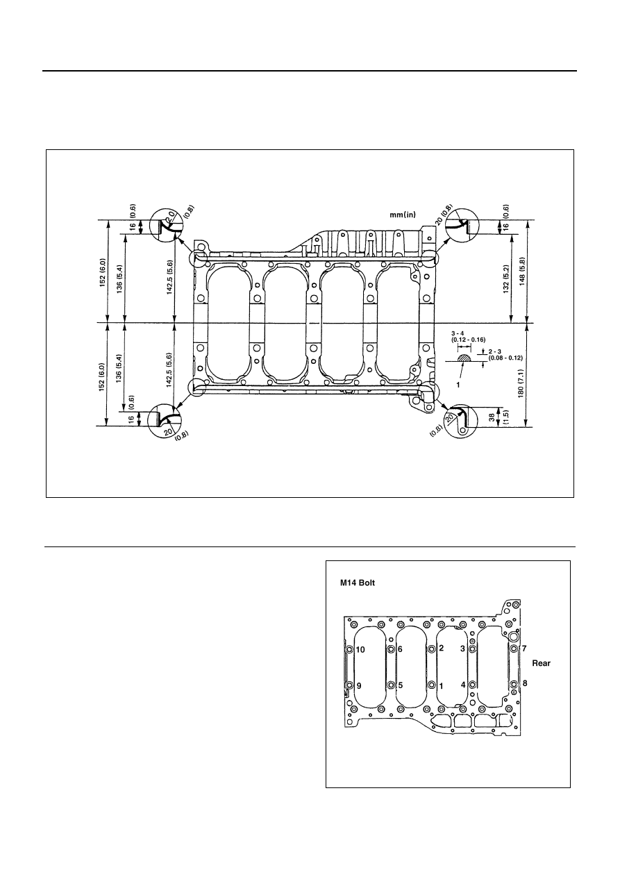
8. Crankcase

1) Apply a 3 mm (0.12 in) bead of recommended

liquid gasket (Three Bond 1207C) or its equiv-
alent to the crankcase upper surface as shown
in the illustration.

2) Carefully place the crankcase on the cylinder

body.

• Install the crankcase within 20 minutes after

application of liquid gasket.

3) Tighten the crankcase to the specified torque in

the numerical order shown in the illustration.

Tighten:
Crankcase bolt (M14: (1) — (10)) to

• 1st step: 98 N

⋅m (10 kg⋅m/72 lb⋅ft)

• 2nd step: 132 N

⋅m (13.5 kg⋅m/98 lb⋅ft)

• 3rd step: 30 — 60

°

Crankcase bolt (M10:(1) — (17)) to 37 N

⋅m (3.8 kg⋅m/27

lb

⋅ft)

Angle gauge: 5-8840-0266-0

Legend

1. Liquid gasket

N6A1622E

N6A1415E

ENGINE (4HF1 / 4HF1-2 / 4HE1-TC / 4HG1 / 4HG1-T) 6A3-117

9. Piston and Connecting Rod Assembly

10. Connecting Rod Lower Bearing
11. Connecting Rod Cap Assembly

Above works refer to “PISTON AND CONNECT-
ING ROD” section in this manual.

12. Oil Pump Assembly
13. Idle Gear A

Above works refer to “OIL PUMP ASSEMBLY”
section in this manual.

14. Flywheel Houisng
15. Power Steering Pump Idle Gear
16. Power Steering Pump Idle Gear Cover
17. Oil Thermo Valve

Above works refer to “TIMING GEAR REPLACE-
MENT” section in this manual.

18. Front Retainer

1) Carefully wipe any foreign material from the cyl-

inder body front face.

2) Apply 2.5 — 3.5 mm (0.10 — 0.14 in) bead of

the recommended liquid gasket (Three Bond
1207C) or its equivalent on the groove of the
front retainer fitting surface shown in the illus-
tration.

3) Install the O-rings (2 pieces) to the front retain-

er.

• Install the front retainer within 7 minutes after

application of liquid gasket.

• For the dislocation of liquid gasket, refer to the

illustration.

4) Align the cylinder body knock pins with the front

retainer knock pin holes.

Tighten:
Front retainer bolt to 24 N

⋅m (2.4 kg⋅m/17 lb⋅ft)

19. Water Pump Assembly

1) Apply 3 — 4 mm (0.12 — 0.16 in) bead of the

recommended liquid gasket (Three Bond
1207C) or its equivalent on the water pump fit-
ting surface.

2) Install the water pump to the front retainer.

Tighten:
Water pump bolt to 24 N

⋅m (2.4 kg⋅m/17 lb⋅ft)

• Install the water pump within 7 minutes after

application of liquid gasket.

• For the dislocation of liquid gasket, refer to the

illustration.

Caution:
The water pump clamping bolt is also used to tighten the
front retainer. So, install the water pump before liquid

N6A0208E

Legend

1. O-ring
2. Liquid gasket

N6A1623E

N6A0234E

6A3-118 ENGINE (4HF1 / 4HF1-2 / 4HE1-TC / 4HG1 / 4HG1-T)

gasket gets dry immediately after installation of the front
retainer.

20. Water Pump Pulley

Tighten:
Water pump pulley bolt to 24 N

⋅m (2.4 kg⋅m/17 lb⋅ft)

21. Oil Pump Strainer

Install the O-ring (1) to the oil pump strainer pipe
and install the oil pump strainer to the cylinder body
shown in the illustration.

Tighten:
Oil pump strainer bolt to 24 N

⋅m (2.4 kg⋅m/17 lb⋅ft)

22. Oil Pan
23. Spacer Rubber 

Above works refer to “OIL PAN” section in this
manual.

24. Crankshaft Rear Slinger
25. Crankshaft Rear Oil Seal

Above works refer to “CRANKSHAFT REAR OIL
SEAL” section in this manual.

26. Flywheel

1) Align the flywheel with the crankshaft knock pin

and temporarily tighten the flywheel bolts.

2) Use the crankshaft stopper to prevent the

crankshaft from turning.
Crankshaft Stopper: 5-8840-2230-0

3) Install the washer and the flywheel bolts and

tighten to the specified torque in numerical or-
der show in the illustration.

Tighten:
Flywheel bolt to

• 1st step: 78 N

⋅m (8.0 kg⋅m/58 lb⋅ft)

• 2nd step: 90 — 120

°

Legend

1. Liquid gasket

Legend

1. Pulley
2. Set plate

N6A1625E

N6A0656E

N6A0657E

ENGINE (4HF1 / 4HF1-2 / 4HE1-TC / 4HG1 / 4HG1-T) 6A3-119

4) Remove the crankshaft stopper.

27. Crankshaft Front Slinger
28. Crankshaft Front Oil Seal

Above works refer to “CRANKSHAFT FRONT OIL
SEAL” section in this manual.

29. Crankshaft Damper Pulley

1) Apply a coat of engine oil to the threads of the

bolts.

2) Align the damper pulley with the crankshaft

knock pin and tighten the bolts to the specified
torque in numerical order.

Tighten:
Damper pulley bolt to 200 N

⋅m (20.4 kg⋅m/147 lb⋅ft)

30. Generator Bracket

Tighten:
Generator bracket bolt to 48 N

⋅m (4.9 kg⋅m/35 lb⋅ft)

31. Fan Belt Adjust Plate

Install the adjust plate and temporarily tighten the
adjust plate bolt.

32. Injection Pump Assembly

Above works refer to “INJECTION PUMP ASSEM-
BLY” section 6C in this manual.

33. Engine Foot

Tighten:
Engine foot bolt to 51 N

⋅m (5.2 kg⋅m/38 lb⋅ft)

Legend

1. Washer
2. Pilot bearing

N6A6504E

N6A0607E

N6A0293E

N6A0292E


Content   ..  364  365  366  367   ..