Isuzu N-Series. Manual - part 331
6A-66 ENGINE MECHANICAL
Disassembly
1. Cylinder Head Assembly
Above works refer to CYLINDER HEAD” section in
this manual.
2. Cylinder Head Gasket
Caution:
Do not reuse the cylinder head gasket.
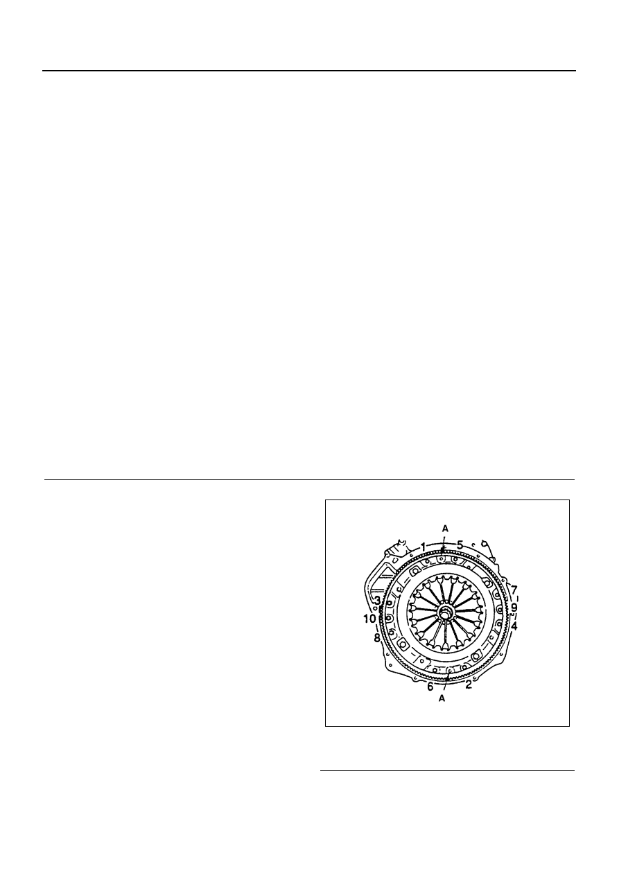
3. Clutch Pressure Plate Assembly
1) Insert the clutch pilot a slinger to the clutch as-
sembly.
Clutch Pilot Aligner: 5-8840-2240-0
2) Loosen the pressure plate bolts in numerical
order a little at a time as shown in the illustra-
tion.
3) Remove the pressure plate assembly.
4. Driven Plate
Remove the driven plate with the clutch pilot align-
er.
Legend
1. Cylinder head assembly
29. Crankshaft rear oil seal
2. Cylinder head gasket
30. Crankshaft rear slinger
3. Clutch pressure plate assembly
31. Spacer rubber
4. Driven plate
32. Oil pan
5. Engine control wire
33. Oil pump strainer
6. Engine control lever assembly
34. Water pump pulley
7. Oil pipe
35. Water pump
8. Oil filter assembly
36. Front retainer
9. Tachometer sensor
37. Oil thermo valve
10. Fuel pipe bracket
38. Power steering pump idle gear cover
11. Vacuum pump oil pipe
39. Power steering pump idle gear
12. Vacuum pump rubber hose
40. Flywheel housing
13. Fan belt
41. Idle gear A
14. Generator
42. Idle gear B
15. Engine foot
43. Idle gear B shaft
16. Injection pump assembly
44. Oil pump assembly
17. Injection pump rubber spacer
45. Connecting rod cap
18. Idle pulley bracket
46. Connecting rod lower bearing
19. Heater pipe
47. Piston and connecting
20. Water suction pipe
48. Crankcase
21. Oil cooler assembly
49. Thrust bearing lower
22. Fan belt adjust plate
50. Crankshaft bearing lower
23. Generator bracket
51. Crankshaft assembly
24. Cover
52. Thrust bearing upper
25. Crankshaft pulley
53. Crankshaft bearing upper
26. Crankshaft front oil seal
54. Piston oil jet
27. Crankshaft front slinger
55. Cylinder block
28. Flywheel assembly
Legend
A. Knock pin
N6A0282E