Isuzu N-Series. Manual - part 329


  Index      Isuzu     Isuzu N-Series - service repair manual


Search            


Content   ..  327  328  329  330   ..


Isuzu N-Series. Manual - part 329


6A-58 ENGINE MECHANICAL

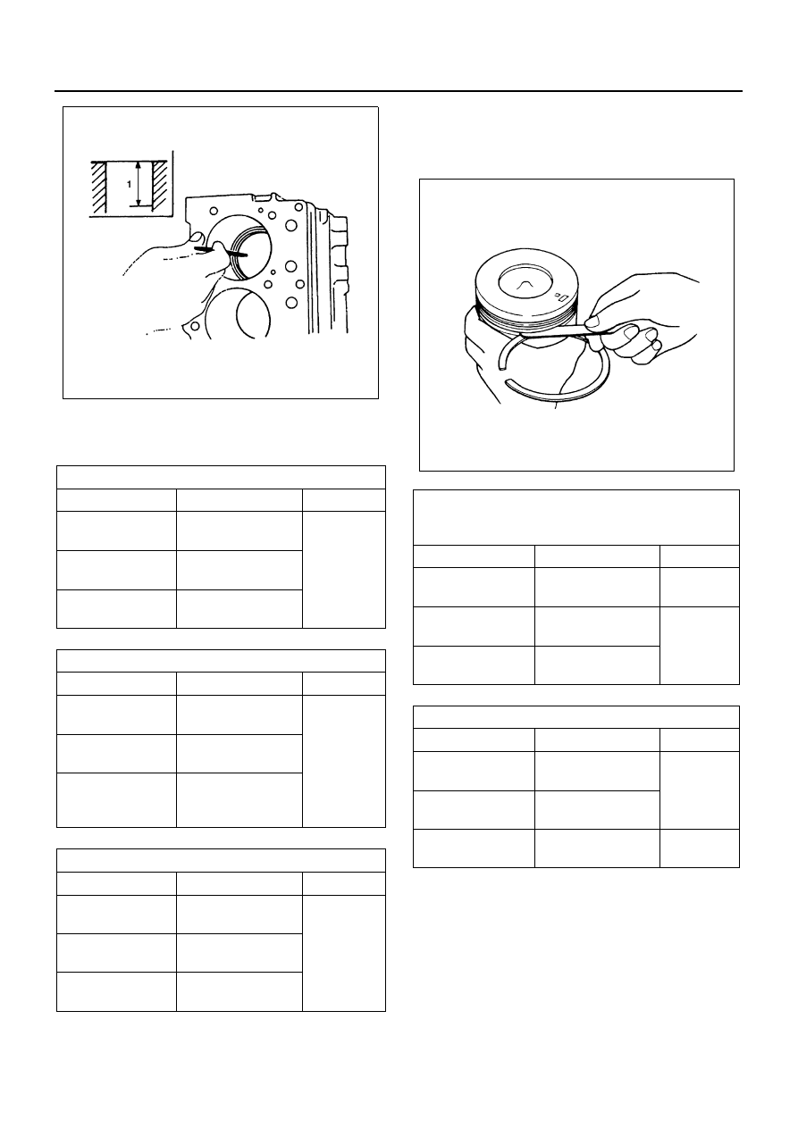
3. Use a feeler gauge to measure the piston ring gap.

If the measured valve exceeds the specified limit,
the piston ring must be replaced.

Piston Ring and Piston Ring Groove Clearance

1. Use a feeler gauge to measure the clearance be-

tween the piston ring and the piston ring groove at
several points around the piston.

2. Visually inspect the piston ring grooves.

If a piston ring groove is damaged or distorted, the
piston must be replaced.

Piston Pin

Piston Pin Diameter
Use a micrometer to measure the piston pin outside di-
ameter at several points.
If the measured value is less than the specified limit, the
piston pin must be replaced.

Piston Ring Gap / 4HF1 / 4HF1-2

mm (in)

Standard

Limit

1st compression
ring gap

0.24 — 0.39 

(0.0094 — 0.0153)

1.50 

(0.0591)

2nd compression
ring gap

0.35 — 0.50 

(0.0138 — 0.0197)

Oil ring gap

0.02 — 0.40 

(0.0008 — 0.0157)

Piston Ring Gap / 4HG1 / 4HG1-T

mm (in)

Standard

Limit

1st compression
ring gap

0.24 — 0.39 

(0.0094 — 0.0153)

1.50 

(0.0591)

2nd compression
ring gap

0.35 — 0.50 

(0.0138 — 0.0197)

Oil ring gap

0.15 — 0.35 

(0.00591 — 

0.0138)

Piston Ring Gap / 4HE1-TC

mm (in)

Standard

Limit

1st compression
ring gap

0.24 — 0.40 

(0.0094 — 0.0157)

1.50 

(0.0591)

2nd and 3rd com-
pression ring gap

0.30 — 0.450 

(0.0118 — 0.0177)

Oil ring gap

0.20 — 0.40 

(0.0078 — 0.0157)

N6A0259E

Piston Ring and Piston Ring Groove 
Clearance / 4HF1, 4HF1-2, 4HG1, 
4HG1-T

mm (in)

Standard

Limit

1st Compression
Ring

0.062 — 0.092 

(0.0024 — 0.0036)

0.20 

(0.0079)

2nd Compression
Ring

0.04 — 0.08 

(0.0015 — 0.0031)

0.15 

(0.0059)

Oil ring gap

0.02 — 0.06 

(0.0008 — 0.0024)

Groove Clearance / 4HE1-TC

mm (in)

Standard

Limit

1st Compression
Ring

0.09 — 0.13 

(0.0035 — 0.0051)

0.20 

(0.0078)

2nd and 3rd Com-
pression Ring

0.09 — 0.13 

(0.0035 — 0.0051)

Oil ring gap

0.03 — 0.07 

(0.0012 — 0.0028)

0.15 

(0.0059)

N6A0260E

ENGINE MECHANICAL 6A-59

Piston Pin Hole and Piston Pin Clearance
Use an inside dial indicator to measure the piston pin
hole (in the piston).

If an inside dial indicator is not available, use the follow-
ing procedure to check the piston pin clearance.

1. Use a piston heater to heat the piston to approxi-

mately 80 — 100

°C (176 — 212°F)

2. Push strongly against the piston pin with your

thumbs. The piston pin should move smoothly with
little or no resistance.

Connecting Rod

Connecting Rod Alignment
Use a connecting rod aligner to measure the distortion
and the parallelism between the connecting rod big end
hole and the connecting rod small end hole.
If either the measured distortion or parallelism exceeds
the specified limit, the connecting rod must be replaced.

Piston Pin Diameter

mm (in)

Engine model

Standard

Limit

Except 4HE1-

TC

35.995 — 

36.000 (1.4171 

— 1.4173)

35.970 (1.4161)

4HE1-TC

39.995 — 

40.000 (1.5746 

— 1.5748)

39.970 (1.5736)

Piston Pin Hole and Pis-
ton Pin Clearance

mm (in)

Standard

Limit

0.004 — 0.017 (0.00016 

— 0.00067)

0.04 (0.0016)

N6A0261E

N6A0262E

Connecting Rod Alignment

mm (in)

Per Length of 100 (3.94)

Standard

Limit

Distortion

0.05 (0.002) or 

less

0.20 (0.008)

Parallelism

N6A0263E

6A-60 ENGINE MECHANICAL

Piston Pin and Connecting rod Small End Bushing
Clearance
Use a caliper calibrator and a dial indicator to measure
the clearance between the piston pin and connecting
rod small end bushing.
If the clearance between the piston pin and the connect-
ing rod small end bushing exceeds the specified limit,
replace the piston pin and/or the connecting rod bush-
ing.

Connecting Rod Bushing Replacement

Connecting Rod Bushing Removal

1. Set the collar (1), the connecting rod (2), and the

collar (3) to the setting bar (4).

Connecting Rod Bushing Replacer: 5-8840-2340-0

2. Hand-tighten the nut (5) until there is no more gap.

3. Set the connecting rod bushing replacer base (6) to

the bench press.

4. Set the connecting rod to the connecting rod bush-

ing replacer base.

5. Tighten the bolt (7).

6. Use the bench press to force the bushing from the

connecting rod.

Connecting Rod Bushing Installation

1. Set the connecting rod bushing replacer base (1) to

the bench press.
Connecting Rod Bushing Replacer: 5-8840-2340-0

2. Set the connecting rod to the connecting rod re-

placer base.
The connecting rod must be perfectly horizontal.

3. Tighten the bolt (2) to hold the connecting rod small

end in place.

Piston Pin and Connect-
ing Rod Small End Bush-
ing Clearance

mm (in)

Standard

Limit

0.012 — 0.027 (0.0005 

— 0.0011)

0.05 (0.002)

N6A0264E

N6A0265E

N6A0266E

N6A0267E

ENGINE MECHANICAL 6A-61

4. Install the two collars (3) and the new bushing (4)

to the setting bar (5).
Align the bushing clinch line and the collar setting
marks.
Tighten the nut (6).

5. Use the bench press to press the new bushing into

position inside the connecting rod.
Check that the bushing oil holes and the connect-
ing rod oil holes are aligned.

6. Use a pinhole grinder to finish the new bushing.

Reassembly

1. Piston
2. Piston Pin Snap Ring

Use a pair of snap ring pliers to install the piston pin
snap ring to the piston.

3. Connecting Rod

1) Clamp the connecting rod in a vise.

Take care not to damage the connecting rod.

2) Install the connecting rod so that the piston

head front mark (1) and the connecting rod
forging mark (projecting) (2) are set in the same
direction.

Connecting Rod Small 
End Bushing Inside 
Diameter

mm (in)

Except 4HE1-TC

36.012 — 36.022 

(1.4178 — 1.4182)

4HE1-TC

40.012 — 40.022 

(1.5753 — 1.5767)

N6A0268E

N6A0269E

N6A0270E

N6A0271E


Content   ..  327  328  329  330   ..