Isuzu N-Series. Manual - part 244


  Index      Isuzu     Isuzu N-Series - service repair manual


Search            


Content   ..  242  243  244  245   ..


Isuzu N-Series. Manual - part 244


ANTI-LOCK BRAKE SYSTEM (ABS) 5A4-41

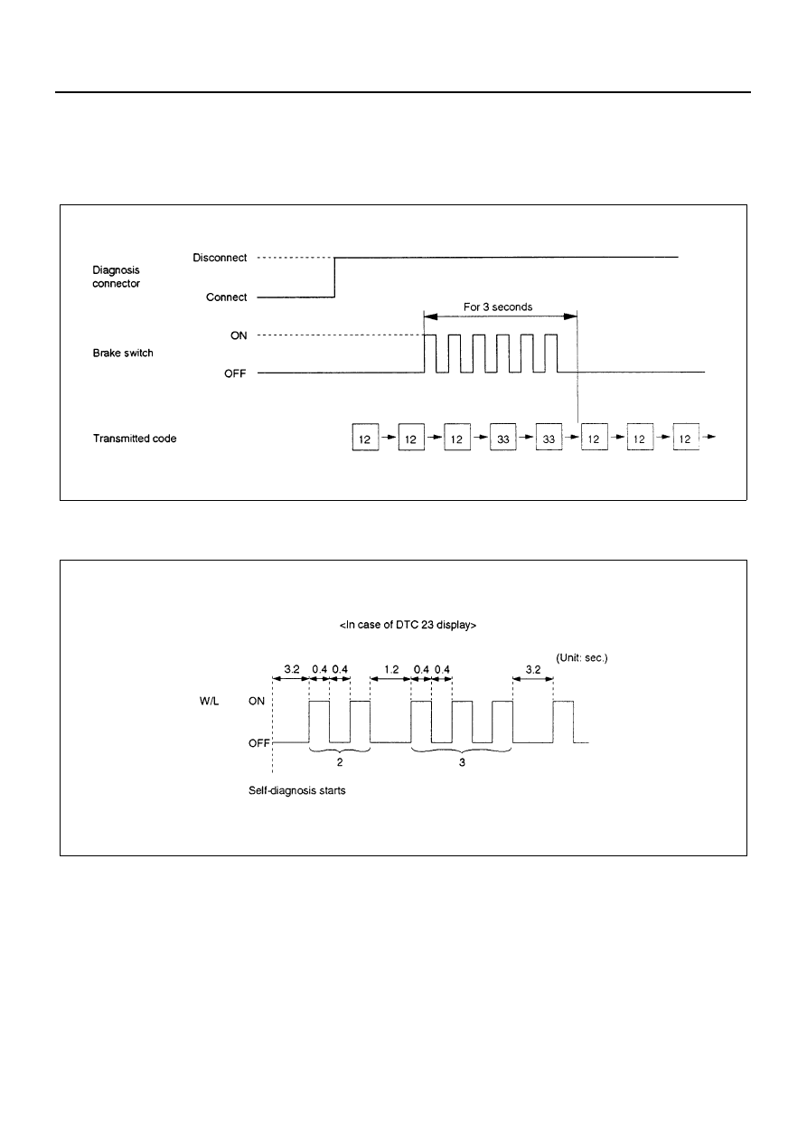
3. How to erase code:

• Conduct brake switch ON/OFF operation 6 or more times within 3 seconds of self-diagnosis startup.
• The code cannot be erased if more than 3 seconds have passed since self-diagnosis startup, or if self-diag-

nosis has started with brake switched on (brake pedal depressed).

• DTCs can be erased also by Tech 2.

4. An example of DTC display

Display of DTC 23

After displaying DTC 12 three times, one DTC after another is displayed, starting with the most recent one. (However,
display is discontinued after about 5 minutes.)
The DTC 12 is displayed repeatedly. (display is discontinued after about 5 minutes)

N5A1035E

N5A1036E

5A4-42 ANTI-LOCK BRAKE SYSTEM (ABS)

5. How to display vehicle model:

1) Turn the key switch OFF.
2) Short the diagnosis connector terminal 12 to

ground.

3) Slightly push the brake pedal.
4) Turn the key switch ON.
5) ABS warning light illuminates.
6) Illuminating number of times indicates the vehi-

cle model.

N5A1037E

Vehicle model

Illuminating number of times

NKR, NPR FRONT 

DISC BRAKE

1

NQR

8

NPR FRONT DRUM 

BRAKE

5

0.4 sec.

0.4 sec.

NPR
FRONT DRUM BRAKE

1.2 sec.

NKR,NPR
FRONT DISC BRAKE

N5A1038E

ANTI-LOCK BRAKE SYSTEM (ABS) 5A4-43

Chart B-1-1 With the key in the ON position (Before starting the engine). Warning light (W/
L) is not activated.

Step

Action

Value(s)

YES

NO

1

Is W/L fuse F-16 blown out?

Go to Step 5

Go to Step 2

2

Is W/L bulb burnt out?

Go to Step 6

Go to Step 3

3

1. Turn the key off.
2. Disconnect EHCU connectors.
3. Turn the key on.
4. Using DVM, measure the voltage be-

tween J-177 EHCU connector terminals 6
and 1.

Does the DVM display a voltage within the
specified value?

12V:

9.5 — 16.5 V

24V:

16.5 — 34 V

Go to Step 4

Go to Step 7

4

Check the continuity between J-177 EHCU
connector terminal 1 and body ground.

Is there continuity?

Go to Step 9

Go to Step 8

5

Replace the fuse.

Is action complete?

Go to Step 10

6

Replace the W/L bulb.

Is action complete?

Go to Step 10

7

Locate and repair open circuit, poor connec-
tion or short circuit in the ignition feed circuit.

Is action complete?

Go to Step 10

8

Locate and repair open circuit, poor connec-
tion or short circuit in the ground circuit.

Is action complete?

Go to Step 10

9

1. Check the harness for suspected discon-

nection.

2. If no fault found, replace the EHCU.

Is action complete?

Go to Step 10

10

1. Reconnect all components, ensure all

components are properly mounted.

2. Clear diagnostic trouble code.

Was this step finished?

Go to “Basic diag-

nostic flow chart”.

5A4-44 ANTI-LOCK BRAKE SYSTEM (ABS)

Chart 1 (DTC13/C0213) Vehicle Type Error

Chart 2 (DTC14/C0214) EHCU Abnormality

Step

Action

Value(s)

YES

NO

1

1. Disconnect EHCU connector.
2. Turn the key on.
3. Measure the voltage at terminal 14, 15,

and 17.

NQR:

All terminal battery 

voltage

NKR, NPR FRONT 

DISC BRAKE:

All terminal 0 V

NPR FRONT DRUM 

BRAKE:

Terminal 14, 15: 0 V

Terminal 17: battery 

voltage

Go to Step 2

Go to Step 5

2

1. Turn the key off and connect EHCU.
2. Connect the Tech 2.
3. Clear the vehicle type.
4. Does the warning light turn off?

Go to Step 3

Replace the 

EHCU.

Go to Step 3

3

Confirm the vehicle type.

Is the vehicle type okay?

Go to Step 4

Replace the 

EHCU.

Go to Step 3

4

Clear the DTC.

Troubleshoot-

ing completed.

5

Repair harness.

Does the warning light turn off?

Go to Step 3

Replace the 

EHCU.

Go to Step 3

Step

Action

Value(s)

YES

NO

1

1. Turn the key off.
2. Disconnect the EHCU connector.
3. Measure continuity between the body

ground and J-177 connector terminal 1,
23.

Is there continuity?

Go to Step 2

Go to Step 3

2

1. Connect the EHCU connector.
2. Clear DTC.
3. Turn the key from off to on and perform di-

agnosis procedure.

Does the DTC repeat?

Go to Step 4

Go to Step 5

3

Repair the open/short circuit or malfunction at
connection of connector.

Is this step completed?

Go to Step 5

4

Replace the EHCU.

Is this step completed?

Go to Step 5

5

1. Install all parts. Verify each part is proper-

ly installed.

2. Clear DTC.

Is this step completed?

Go to “Basic 

diagnostic flow 

chart”.


Content   ..  242  243  244  245   ..