Isuzu N-Series. Manual - part 216


  Index      Isuzu     Isuzu N-Series - service repair manual


Search            


Content   ..  214  215  216  217   ..


Isuzu N-Series. Manual - part 216


HYDRAULIC BRAKES 5A-23

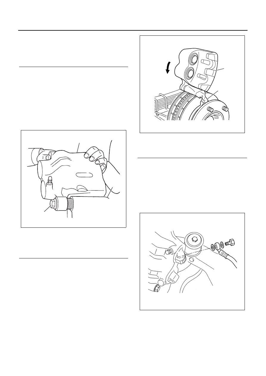
7. Caliper Assembly and Bolt (Lock pin side)

• Install the caliper assembly to the support as-

sembly guide pin from the inside.

• Return the caliper assembly to its original posi-

tion.

• Tighten the bolt (lock pin side) to the specified

torque.

Tighten:
Bolt (Lock pin side) to 125 N

⋅m (12.7 kg⋅m / 92 lb⋅ft).

8. Flexible Hose

• Tighten the flexible hose bolt to the specified

torque.

Tighten:
Hose bolt to 34 N

⋅m (3.5 kg⋅m / 25 lb⋅ft).

Air Bleeding

Refer to “Brake Bleeding” in Section 00 of section.

Legend

1. Pin Boss of Support
2. Support Assembly
3. Pin Boot
4. Pin

Legend

1. Caliper Assembly
2. Support Assembly
3. Pin Bolt

3

1

2

N5A0432E

Legend

1. Caliper Assembly
2. Support Assembly

1

2

N5A0443E

N5A0444E

5A-24 HYDRAULIC BRAKES

Front Disc Brake Pad

Removal

Notice:

• Block vehicle wheels and apply the parking brake.
• Rise the axle to clear the tire from the ground.

Position jack stands under vehicle.

• Remove the wheel.

1. Loosen and remove the lock pin bolt from the lower

side of the caliper.

2. Turn the caliper assembly up and wire it to the

frame firmly so that the hose is not stretched.

Notice:

• Do not disconnect the brake hose.

3. Remove the pad assembly with clips.
4. Conduct disc wear check, and resurface or replace

it as required.

5. When removing brake disc, slide caliper assembly

inside of the vehicle, and take out brake disc from
support assembly.

Take care not to wipe the special grease from
guide pin, and prevent from sticking dust or any for-
eign material to guide pin.

6. Refer to Section 4C FRONT AXLE and Section 3C

FRONT SUSPENSION for disc wear check and re-
placement procedures.

Installation

1. Keep the rotor face away from the brake oil or

grease.

2. Use a hand vise to push the piston backward until

it reaches the cylinder bottom, as the piston was
pushed forward by the distance where the pad
worn.

Notice:

• When using a hand vise, push the piston at its cen-

ter.

3. Remove hand vise and install the new pads along

with new clips.

Notice:

• Be careful not to assemble the inner and outer pad

reversely.

4. Install the bolt (Lock pin side) into the lock pin by

turning the caliper carefully so that the piston boot
and pin boot may not be wedged. 
After assembling the caliper assembly, make sure
that the piston boot and pin boot fitted correctly,
and not damaged.

Legend

1. Lock Pin
2. Inner Pad
3. Outer Pad
4. Caliper Assembly
5. Support Assembly

1

2

3

4

5

N5A0445E

Legend

1. Steel Plate
2. Caliper Assembly
3. Piston
4. Hand Vise

2

1

3

4

N5A0446E

HYDRAULIC BRAKES 5A-25

Independent Suspension Models (NKR)

Legend

1. Joint bolt and flexible hose

7. Support assembly

2. Lock pin bolt

8. Boot ring

3. Guide pin bolt

9. Piston boot

4. Caliper assembly

10. Piston

5. Pad

11. Piston seal

6. Pad clip

N5A0112E

5A-26 HYDRAULIC BRAKES

Removal

1. Joint bolt and Flexible Hose 
2. Lock Pin Bolt
3. Guide Pin Bolt
4. Caliper Assembly

5. Pad

6. Pad Clip

7. Support Assembly

8. Boot Ring
9. Piston Boot

10. Piston

1) Place a piece of wood across the body assem-

bly to prevent piston damage.

2) Apply approximately 196 kPa (2 kg/cm

2

 / 28.4

psi) of compressed air to the body assembly oil
port to remove the pistons.

N5A0113E

N5A0114E

N5A0115E

N5A0116E


Content   ..  214  215  216  217   ..