Isuzu N-Series. Manual - part 211
HYDRAULIC BRAKES 5A-3
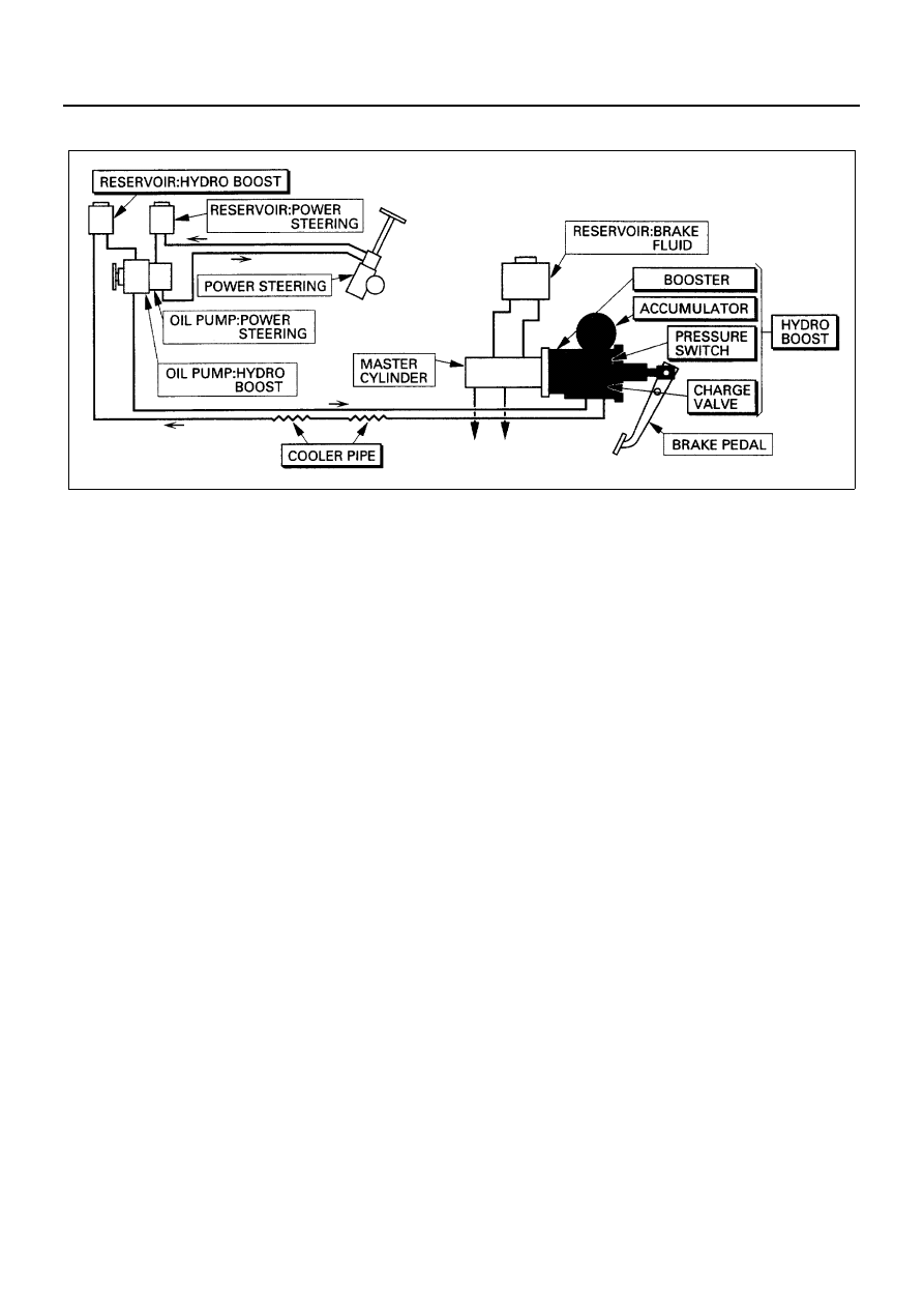
Hydraulic Booster Brake system
The hydro boost system, which functions as a brake
force boosting device that allows the brake to be operat-
ed with less force than otherwise, includes the hydro
boost, which has the booster, accumulator, charge
valve, and pressure switch in an integrated structure, a
reservoir, and a cooler pipe.
Functions of the Main Constituent Parts
Booster:
Controls the hydraulic oil ejected from the oil pump and
amplifies the force on the pedal.
Accumulator:
Accumulates the hydraulic oil under pressure for the
boosting operation after the pump stops.
Charge valve:
Performs switching operation and feeds the hydraulic oil
to the accumulator when the accumulator oil pressure
declines.
Pressure switch:
Detects that the accumulator oil pressure has declined
to the warning set pressure and operates the warning
buzzer.
Oil pump:
Is driven by the engine rotation and feeds the hydraulic
oil to the hydro boost through the piping.
Reservoir:
The pump stores the hydraulic oil for doing suction and
expulsion.
Cooler pipe:
Located before the radiator, facilitates heat radiation of
the hydraulic oil in the system piping, and inhibits an in-
crease in the temperature of the oil.
Other units relating to this system include, as shown in
the figure, the power steering, the pump and reservoir
for the power steering, the master cylinder, which re-
ceives the output of the hydro boost and activates the
brake, the reservoir for the master cylinder, and the
brake pedal that activates the booster.
The master cylinder is integrally bolted to the booster of
the hydro boost. The pump for the power steering is in-
tegrated as a tandem pump that shares the hydro boost
pump and the drive unit. But as systems, the hydro
boost and the power steering are independent of each
other, and their reservoirs are separate as well.
Booster Assembly
The hydraulic booster is a device that applies force to
the master cylinder when the brake pedal is applied. The
fluid flowing through the booster head is controlled by
brake pedal movement.
The hydraulic booster cylinder rod attaches to a piston
that connects with the spool valve. This assembly
moves when brake pedal pressure is applied. The spool
valve restricts fluid flow and builds pressure on one side
of the piston. The pressure overcomes the return spring
and moves the piston to a balanced position. As the pis-
ton moves, it pushes the cylinder rod and applies pres-
sure to the master cylinder.
A relief valve inside the pump limits the pressure to
11,770 kPa (120 kg/cm
2
/ 1707 psi). This pressure level
provides good braking without damaging the brake
pipes or hoses. When actuated, the relief valve allows
fluid to bypass the piston.
Fluid and Fluid Handling
This system uses no special fluids. However, care must
be taken to use the correct fluids. The master cylinder
and brake system uses brake fluid, while the hydraulic
brake booster pump uses power steering fluid.
N5A0045E