Isuzu N-Series. Manual - part 191


  Index      Isuzu     Isuzu N-Series - service repair manual


Search            


Content   ..  189  190  191  192   ..


Isuzu N-Series. Manual - part 191


FRONT AXLE 4C-59

18. Tie Rod End
19. Front Drive Shaft Assembly
20. Spindle
21. Front Brake Assembly

22. Front Axle Hub, Brake Drum and Relative Parts

Refer to “FRONT HUB and BRAKE DRUM (4 

× 4

Model)” previously in this section.

23. Front Locking Hub Set

Refer to “FREE WHEEL HUB” previously in this
section.

24. Wheel and Tire

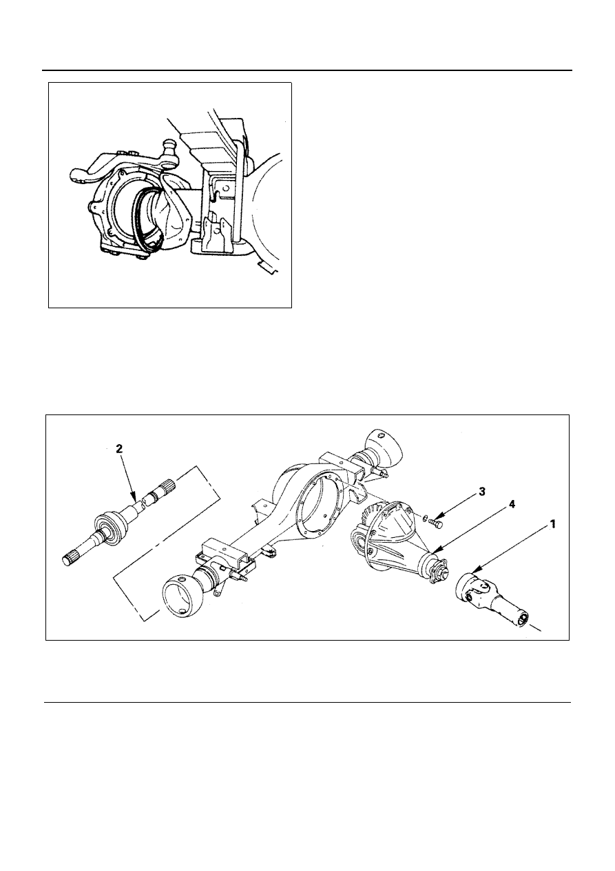
Front Differential Assembly (4 

× 4 Model)

N4A0397E

Legend

1. Propeller shaft assembly

3. Front axle case bolt

2. Front drive shaft assembly

4. Front differential assembly

N4A0398E

4C-60 FRONT AXLE

Removal

Support the front axle with a suitable jack and chassis
stands.
Drain the front axle case by removing the drain plug on
the lower part of the front axle case.

1. Propeller Shaft Assembly

Remove the propeller shaft assembly.

2. Front Drive Shaft Assembly

Refer to “Spindle and Drive Shaft” previously in this
section.

3. Front Axle Case Bolt

Put jack under the center of front axle then remove
the front axle case bolts.

4. Front Differential Assembly

Remove the front differential assembly from the
front axle case.

Installation

1. Front Differential Assembly

Clean the faces of the front axle case and the final
drive carrier.
Apply the recommended liquid gasket (Three Bond
1215 or its equivalent) to the sealing side of the
front axle case and the final drive carrier.

2. Front Axle Case Bolt

Attach the front final drive assembly to the front
axle case and tighten the bolts.

Tighten:
Front axle case bolt to 67 N

⋅m (6.8 kg⋅m / 49 lb⋅ft)

3. Front Drive Shaft Assembly
4. Propeller Shaft Assembly

Fill the axle case with hypoid gear lubricant to just
below the filler hole.

Lubricant capacity, 2.7 liter (2.9 US qt / 2.4 Imp qt)

N4A0399E

FRONT AXLE 4C-61

Front Axle Assembly (4 

× 4 Model)

Legend

1. Wheel and tire

5. Brake flexible hose

2. Shock absorber

6. Stabilizer assembly

3. Drag link

7. Front propeller shaft

4. Tie rod assembly

8. Leaf spring U-bolt

N4A0400E

4C-62 FRONT AXLE

Removal

Preparation:
Jack up and support the vehicle on stands.

1. Wheel and Tire
2. Shock Absorber

Remove lower side of shock absorber.

3. Drag Link

Remove the drag link (on the knuckle arm side).

4. Tie Rod Assembly

Remove the tie rod assembly (with relay lever at-
tached). Refer to STEERING LINKAGE (4 

×  4

Model) in section 3B.

5. Brake Flexible Hose

Remove a clip on the brake hose bracket.
After the hose is disconnected, prevent brake fluid
running out and invasion of foreign matters.

6. Stabilizer Assembly

Refer to STABILIZER in section 3C.

7. Front Propeller Shaft

Draw setting marks (1) on the front and rear flang-
es.
Also, draw setting marks as shown if the propeller
shaft is removed at the spline yoke.

8. Leaf Spring U-Bolt

1) Put jack under the center part of front axle then

remove the U-bolts.

2) Lower the front axle assembly and roll out to-

ward the front of vehicle.
Use care so as not to cause damage to brake
hose, back plate and front axle tube end boot.

9. Front Axle Assembly

Installation

1. Front Axle Assembly
2. Leaf Spring U-Bolt

Align a hole in the center of spring seat in the front
axle case with the center bolt of leaf spring, and
tighten the leaf spring U-bolt.

N4A0401E

N4A0402E

N4A0403E

N4A0404E


Content   ..  189  190  191  192   ..