Isuzu N-Series. Manual - part 190
FRONT AXLE 4C-55
Inspection and Repair
Make the necessary adjustments, repairs, and part re-
placements if excessive wear or damage is discovered
during inspection.
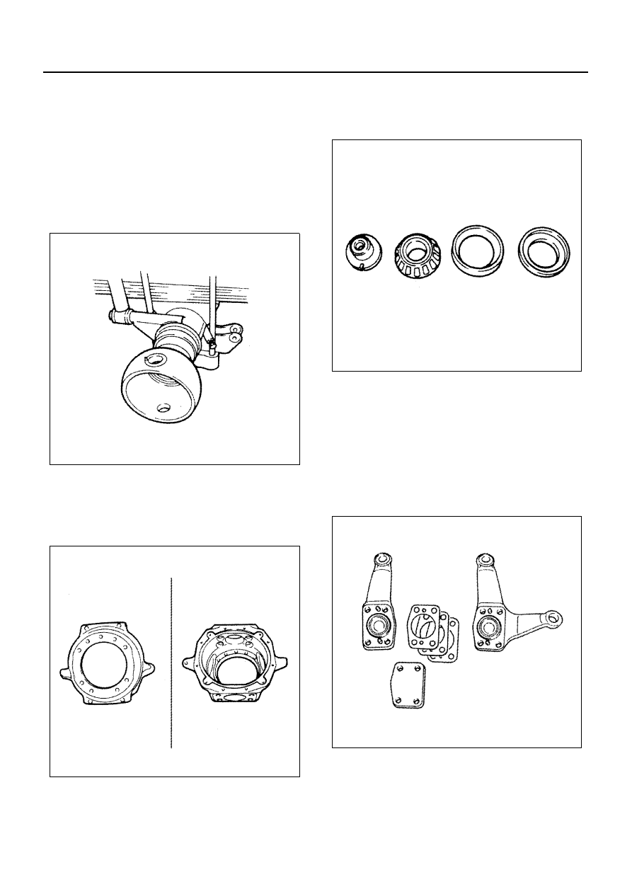
Front Axle Tube End
Inspect the front axle case tube end sphere for crack,
wear, damage or rust. Slight rust of sphere should be
polished with a sand paper.
To check the tube end sphere for crack, use a red-check
or a magnetic flaw detector.
If a crack is found, replace the front axle case assembly.
Front Axle Knuckle
Inspect the whole of the knuckle for cracks, wear or
damage using a magnetic flaw detector or red-check.
Replace the knuckle if any abnormal condition is notice-
able.
King Pin
Inspect the king pin for cracks.
Use a magnetic flaw detector or red-check.
Replace king pin, if any cracks are found.
King Pin Bearing
Inspect the bearing for wear, seizure, damage and
rough rotation.
Replace any flawed or damaged bearing.
Knuckle Arm
Tie Rod Arm
King Pin Cover
Inspect the knuckle arm, tie rod arm and king pin cover
for cracks, damage or wear.
Replace the these parts if any abnormal condition is
noticeable.
To check the arm for crack, use a visible dye-penetrant
flaw detection method or a magnetic flaw detector.
Replace the arm if a crack is found.
Front Axle Tube End Boot
Inspect the front axle tube end boot and replace if
broken. It should be replaced if even one hole or crack is
found.
Oil Seal
Inspect the oil seal, and replace it if its lip is damaged,
worn or hardened.
N4A0376E
N4A0377E
N4A0378E
N4A0379E