Isuzu N-Series. Manual - part 188


  Index      Isuzu     Isuzu N-Series - service repair manual


Search            


Content   ..  186  187  188  189   ..


Isuzu N-Series. Manual - part 188


FRONT AXLE 4C-47

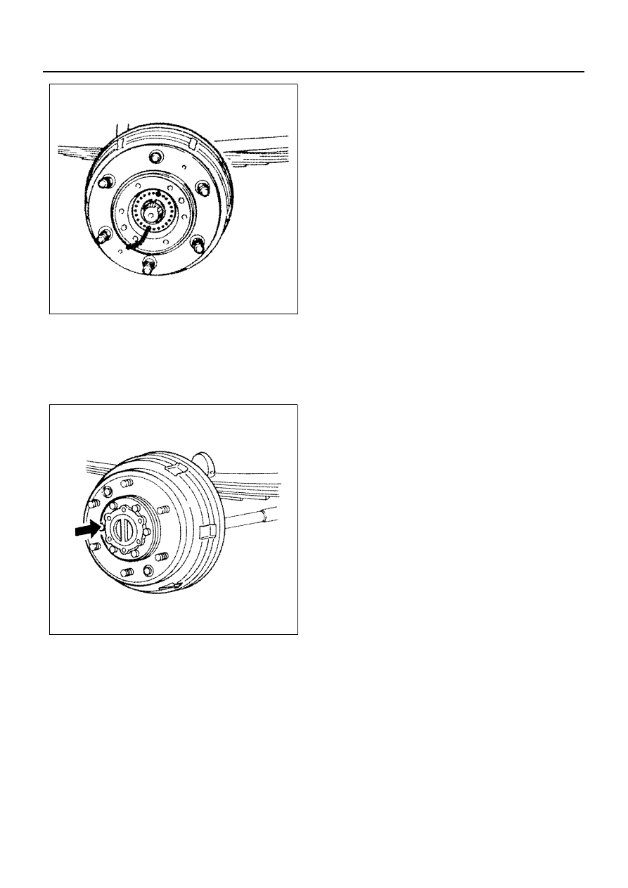
13. Front Locking Hub Set

Refer to “FREE WHEEL HUB” previously in this
section.

Tighten:
Front locking hub set bolt to 98 N

⋅m (10.0 kg⋅m / 72 lb⋅ft)

14. Wheel and Tire

N4A0357E

N4A0358E

4C-48 FRONT AXLE

Spindle and Drive Shaft (4 

× 4 Model)

Legend

1. Wheel and tire

4. Front brake assembly

2. Front locking hub set

5. Spindle

3. Front axle hub, brake drum and related parts

6. Front drive shaft assembly

N4A0359E

FRONT AXLE 4C-49

Removal

Preparation:
Jack up and support the vehicle on stands.

1. Wheel and Tire
2. Front Locking Hub Set

Refer to “FREE WHEEL HUB” previously in this
section.

3. Front Axle Hub, Brake Drum and Related Parts

Refer to “FRONT HUB and BRAKE DRUM (4 

× 4

Model)” previously in this section.

4. Front Brake Assembly

1) Remove fixing bolts and front oil shield cover,

then the brake assembly.
The front oil shield cover, spindle and back
plate are tightened together.

2) Using a wire, sling the brake assembly to the

frame to hold. At this time, take care not to
damage or bend the brake hose.

5. Spindle

Hitting lightly the spindle end with a wood or plastic
hammer, remove the spindle from knuckle.
Do not use an iron hammer. Special care should be
taken to protect the threads at the spindle end from
damage.

6. Front Drive Shaft Assembly

Pull and remove the front drive shaft to your side.

Inspection and Repair

Make the necessary adjustments, repairs, and part re-
placements if excessive wear or damage is discovered
during inspection.
Spindle

1. Inspect the whole of the spindle for crack, wear or

damage.
Replace the spindle if any abnormal condition is
noticeable.
Use a visible dye-penetrant flaw detection method
or a magnetic flaw detector.

N4A0360E

N4A0361E

N4A0362E

4C-50 FRONT AXLE

2. Inspect the front axle shaft thrust washer or bush-

ing for wear and damage.

Front Drive Shaft Assembly

1. Inspect the front drive shaft for bending or distor-

tion.

2. Inspect the front drive shaft spline for wear or dis-

tortion.
Replace the front drive shaft assembly if wear or
distortion is found.

3. Inspect the stopper contact face (on the spindle’s

side) for wear or damage.

N4A0363E

N4A0364E

N4A0365E

N4A0099E


Content   ..  186  187  188  189   ..