Isuzu N-Series. Manual - part 159


  Index      Isuzu     Isuzu N-Series - service repair manual


Search            


Content   ..  157  158  159  160   ..


Isuzu N-Series. Manual - part 159


PROPELLER SHAFT 4A-11

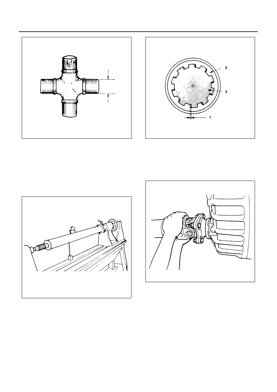
Propeller Shaft Run-Out
Support the propeller shaft at its ends and check for run-
out by holding the probe of a dial indicator agains the
center part of the shaft.
If the amount of run-out it beyond the standard value for
assembly, correct with a bench press or replace with a
new one.
Standard: 0.5 mm (0.02 in) or less
Limit: 1.0 mm (0.039 in)

Play in Splines in Normal Direction of Rotation
Check the amount of play (1) in the sleeve yoke (2) and
propeller shaft (3) splines in direction of rotation using a
pointed feeler gauge.
Standard: 0.1 mm (0.0039 in)
Limit: 0.3 mm (0.012 in)

Checking of Play of Double Cardan Joint (Front Pro-
peller Shaft Only)

1. Check the double cardan joint for play in the direc-

tion of the spider (1) shaft. When there is an exces-
sive play found, replace it as a propeller shaft
assembly.

N4A0030E

N4A0031E

N4A0032E

N4A0033E

4A-12 PROPELLER SHAFT

Preload Checking of The Double Cardan Joint (Front
Propeller Shaft Only)

1) As shown in the illustration, tie a wire firmly by

passing it through the bolt holes which are in
the same direction with the flange yoke shaft.

2) Hook a spring balance at the center of the wire,

and pull the spring balance in the direction of a
right angle.

3) Measure the value and check if the reading of

the spring balance is within the specified value
at the moment when the flange starts to move.

Preload, 52 N (5.3 kg / 11.7 lb)
Lubrication
Universal Joints
Universal joints are drilled and provided with a lubrica-
tion fitting through which the lubricant travels to all four
bearing caps, direct to the needle bearing.
Needle bearings are protected against lubricant leakage
and the entrance of foreign matter by seals.

1) Lubricate with a chassis lubricant.

2) When greasing the joint, a flow of grease at all

four trunnion seals must be visible to ensure lu-
brication of the U-joint. If grease does not ap-
pear at all four trunnion seals, the universal
joint should be rotated while applying lubricant
under pressure to relieve any air lock inside the
joint which would prevent lubricant from reach-
ing the bearing area.

Sliding Spline Sections
Apply grease gun pressure to the lubrication fitting until
lubricant appears at the pressure relief hole (1) as
shown in the figure. Now cover the pressure relief hole
with your finger and continue to apply pressure until
grease appears at the sleeve yoke seal as shown in the
figure.

Reassembly

1. Flange Yoke

The flange yoke at end of the propeller shaft should
be in alignment with the spline yoke as illustrated. 
The direction of the flange yoke at each end of the
propeller shafts (setting mark) are in alignment.

N4A0034E

N4A0035E

N4A0036E

N4A0037E

PROPELLER SHAFT 4A-13

2. Spider
3. Needle Roller Bearing

Apply MoS

2

 grease to lip of the oil seal and needle

roller bearing.

Notice:

Excessive greasing could make the bearing difficult to
install or make accurate data unobtainable for the selec-
tion of the right snap ring.

Assemble the spider to the flange yoke. Using the
spider as a guide, install the needle roller bearing
into the hole in the arm of the flange yoke by press
or tapping with a soft-faced hammer.

Caution:

• The needle roller bearing cannot be installed

smoothly if is set at an incorrect angle with the
flange.

• Excessive hammering will damage the needle roll-

er bearing.

Eliminate the clearance between snap ring and bearing
by striking the yoke with a hammer.

Align setting marks and join the yokes.

Legend

1. Correct
2. Incorrect

N4A0416E

N4A0039E

N4A0040E

4A-14 PROPELLER SHAFT

4. Snap Ring

Discard used snap ring and install new one. 
When the bearing is fitted into position, select and install
the snap ring of suitable thickness so that the end play
of the spider pin is held within 0.1 mm.

Notice:

Be sure to use snap rings of the same thickness on both
sides.

5. Grease Fitting

Install the grease fitting at an angle of approximately 40
degrees to the spider. The parts should be so installed
that all grease fittings are pointed upward.

Thickness of Snap Ring Available

 mm (in.)

NHR, NKR55

Snap ring thickness

Identification color

1.5 (0.059)

Blue

1.53 (0.060)

White

1.59 (0.063)

Yellow

1.62 (0.064)

Green

1.68 (0.066)

Not colored

NKR 66, 71, 77, NPR 66, 70, 77, 

NQR66, 71, NPS 71

Snap ring thickness

Identification color

1.95 (0.077)

Blue

2.00 (0.079)

White

2.05 (0.081)

Yellow or Not colored

N4A0041E

N4A0042E

N4A0043E


Content   ..  157  158  159  160   ..