Isuzu N-Series. Manual - part 158


  Index      Isuzu     Isuzu N-Series - service repair manual


Search            


Content   ..  156  157  158  159   ..


Isuzu N-Series. Manual - part 158


PROPELLER SHAFT 4A-7

5. Center Bearing Side Nut

Tighten:

Center bearing bracket bolt to 40 N

⋅m (4.1 kg⋅m / 30 lb⋅ft)

6. Differential Side Nut

Tighten:

Differential side nut to

• M10: 63 N

⋅m (6.4 kg⋅m / 46 lb⋅ft)

• M12: 103 N

⋅m (10.5 kg⋅m / 76 lb⋅ft)

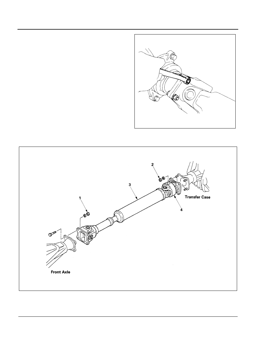
Front Drive Propeller Shaft

N4A0023E

Legend

1. Differential side nut

3. Propeller shaft assembly

2. Transfer case side nut

4. Double cardan joint

N4A0024E

4A-8 PROPELLER SHAFT

Removal

Preparation:
Since the propeller shaft assembly is carefully balanced,
a setting mark should be applied to the joints, before re-
moval in to original position.

1. Differential Side Nut
2. Transfer Case Side Nut
3. Propeller Shaft Assembly

Notice:

• The double cardan joint can not be disassembled.

When it is defective, replace it as a propeller shaft
assembly.

• Be sure not to bend double cardan joint at an angle

of 25

° or more. Further, be careful removing or car-

rying the assembly not to shock the double cardan
joint.

Installation

1. Propeller Shaft Assembly
2. Transfer Case Side Nut

Tighten:

Transfer case side nut to

• M10: 62.7 N

⋅m (6.4 kg⋅m / 46.3 lb⋅ft)

3. Differential Side Nut

Tighten:

Differential side nut to

• M10: 62.7 N

⋅m (6.4 kg⋅m / 46.3 lb⋅ft)

Legend

1. Front differential
2. Setting mark
3. Double cardan joint
4. Transfer

N4A0025E

PROPELLER SHAFT 4A-9

UNIT REPAIR

Universal Joint

Legend

A. Inside Type 

NHR
NKR 55

1. Grease fitting
2. Snap ring
3. Needle roller bearing

B. Outside Type

NKR 66,71,77
NPR 66,70,77
NQR 66
NPS 71

4. Spider
5. Flange yoke

N4A0026E

4A-10 PROPELLER SHAFT

Disassembly

Preparation:
Since the propeller shaft assembly is carefully balanced,
a setting mark (1) should be applied to the joints, before
disassembly.

1. Grease Fitting
2. Snap Ring
3. Needle Roller Bearing

Tap out the bearing by applying a shock to the shoulder
of the yoke, using a copper hammer.
Remove the needle roller bearings remaining in position
by tapping lightly on the spider.
Remove the remaining bearings in the similar manner.

4. Spider
5. Flange Yoke

Inspection and Repair

Make necessary correction or parts replacement if wear,
damage or any other abnormal conditions are found
through inspection.
Visual Check
Inspect following parts for wear, damage or other abnor-
mal conditions.

Notice:

When any part of the journal assembly requires replace-
ment, be sure to replace the entire assembly.

• Spider
• Needle roller bearing
• Yoke
• Flange
• Center bearing
• Cushioning rubber
• Bracket

Outside Diameter of Spider Pins

N4A0027E

mm (in.)

Standard

Limit

NHR, NKR55

18.46 (0.73)

18.36 (0.72)

NKR 66,71,77
NPR 66, 70,77
NQR66, 71,NPS 71

21.94 (0.86)

21.84 (0.8598)

NQR70, 75
NPR75
NPS75

24.00 (0.945)

23.9 (0.941)

N4A0028E


Content   ..  156  157  158  159   ..