Isuzu N-Series. Manual - part 135
STEERING LINKAGE 3B3-9
7. Bolt, Nut, Washer and Cotter Pin
8. Relay Lever
9. Tie Rod End
10. Lock Nut
11. Tie Rod Tube
12. Lock Nut
13. Tie Rod
Inspection and Repair
Make necessary correction or parts replacement if wear,
damage, or any other abnormal conditions are found
through inspection.
Tie Rod End
• Inspect the ball joint taper fitting part for contact
condition or abnormal wear.
• Inspect the boot for damage or grease leak.
• Move the ball joint to confirm its normal movement.
• If abnormal condition is found, replace the assem-
bly because it cannot be disassembled.
Tie Rod
Inspect the tie rod tube for bending or damaged threads.
If abnormal condition is found, replace the assembly or
correct if bending is small.
Relay Lever
Inspect the relay lever bushing. If bushing is defective,
replace the relay lever assembly.
Installation
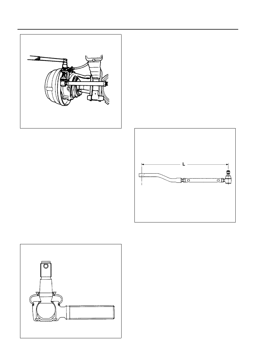
1. Tie Rod
2. Lock Nut
3. Tie Rod Tube
4. Lock Nut
5. Tie Rod End
1) Install all parts and adjust tie rod length (L).
Tie Rod Length (L)
781 mm (30.748 in)
2) After adjustment, tighten lock nuts temporarily.
6. Relay Lever
7. Bolt, Nut, Washer and Cotter Pin
1) Install the relay lever to the bracket.
2) Tighten the nut to specified torque, with just
enough additional torque to align cotter pin
hole.
3) Install new cotter pin.
Tighten:
• Relay lever nut to 147 N
⋅m (15 kg⋅m / 108 lb⋅ft)
N3A0312E
N3A0307E
N3A0314E