Isuzu N-Series. Manual - part 1268


  Index      Isuzu     Isuzu N-Series - service repair manual


Search            


Content   ..  1266  1267  1268  1269   ..


Isuzu N-Series. Manual - part 1268


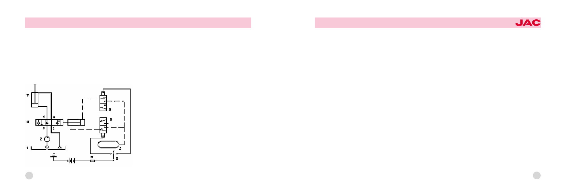
Diagram 5 illustrates the working principle of power take-off control system. When the switch is turned on, the com鄄
pressed air in the reservoir will flow to the power take-off cylinder through the electromagnetic valve, which will push the
gear of the power take-off to mesh with the gear of the transmission. When the power is turned off, the air in the cylin鄄
der袁under the influence of the return spring of the power take -off cylinder, will be discharged into the environment
through the vent of electromagnetic valve. The gear of the power take-off will be separated from that of the transmis鄄
sion, cutting off the power of the pump.
音 The hydraulic principle diagram of dumping system

1. hydraulic oil tank
2. gear pump
3. electromagnetic gas valve
4. air tank
5. 3-gang switch
6. air slide valve
7. hydraulic oil tub
8. the fuse

196

OWNER爷S MANUAL

JAC HEAVY DUTY TRUCK

Diagram 6 shows the hydraulic principle of the dumping system. From it we can see that the carriages in the system can
pause or fall down, free of the influences of the oil pump's working conditions. Namely, as the carriages are being
paused or falling, the oil pump can still be at work. The simplification of the operation in the pausing condition is achiev鄄
able. The air slide valve, numbered 6, which is factually a 5/4 way air control valve, helps lift, pause or drop the car鄄
riages by means of the switch (numbered 5). When the air control valve is on the left, the hydraulic oil flows through the
oil tank (1), the gear pump (2), and "P"& "A": the entrances to the air control valve fall down towards the bottom of the oil
tub, the carriages are lifted. The oil on the upper part of the tub, however, retreats to the tank by way of "B" &"O". In the
case where the air control valve is in the middle (as is signified in the diagram), the line along which the hydraulic oil fi鄄
nally returns to the tank consists of the tank, the bump gear and entrances "P"& "O"; now the carriages are paused. On
the right as the air control valve is (the carriages having been raised), part of the oil, due to the gravity of the carriages,
comes back through entrances "A"& "O" to the tank; still a certain amount of the oil goes back, passing the tank, the
bump gear and entrances P&O. Meanwhile, the downward movement of the tank's pistol renders the upper part of the
tank vacuum. Some oil, under this situation, enters the upper part of the tank through entrance B.

197

2. The operational methods
音 The PTO (Power Take Off) System
Get the engine started and make sure if it is at usual work; remember not to invigorate the gearlever. The moment the air
pressure gauge tells that the air pressure of the brake system exceeds 0.4Mpa, separate the clutch, and then, a few
seconds after the power is cut off, give a press to the button, which serves as the self-lock switch of the PTO, to turn it
on. Afterwards, slowly put through the clutch. With all of the above-mentioned procedures done, the oil pump, driven by
the PTO output shaft, is set in motion. To remove it out of work, just separate the clutch and press the button to turn off
the PTO.
音 The Lifting of the Carriages
With the oil pump at work, press the self-lock switch button for lifting and transfer the handle from "O" to "lifting", the
carriages are so raised. When they reach the most possible height, the lifting itself is no longer under way, because of
the automatic oil spill of the system. The speed of the lifting, though, is in direct proportion with that of the engine's ro鄄
tating. What should be heeded is that it is inadvisable for the carriages to be lifted too fast. Mostly, for the lifting, the en鄄
gine needs to be set under the condition of medium accelerograph, and the engine's rotating speed should be kept be鄄
low the maximum, in case the oil pump should rotate over fast, thus bringing about self-damage.
音 Bringing -down and Relocating the Carriages
As soon as the carriages are unloaded, the quicker they are brought down the better they are relocated. Press the self-
lock switch button for lifting, turn the handles from "lifting", past "O", to "bringing down", then the carriages go into gradu鄄
al falling until the final relocation comes. Now, again press the button and maintain the handles of lifting and TPO at "O";

198

OWNER爷S MANUAL

JAC HEAVY DUTY TRUCK

the vehicle gets started without delay; and the accidental lifting of carriages is simply out of question.
音 The Pausing of the Carriages
Suppose you want them to stop at a certain angle (0耀48毅) when they are being lifted or bought down, what you need to
do is merely to turn the lifting switch to "O". A momentary pause does not claim the cut-off of the PTO power, which di鄄
minishes the degree of the operational complication. Long-time pausing, however, asks for the cut-off of the power;
such being the case, the pump quits working. Therefore, improper operating which harbors accidents is hampered and
the amount of unnecessary oil-consuming finds itself reduced.
Notice: You ought to bear in mind that the controlling switch of TPO complies with electricity -liquid circuit and that of the
lifting electricity-gas-liquid circuit. So, when it comes to operating, the voltage of the battery must stay at no less than
24V and the air pressure of the gas container at no less than 0.4Mpa. Otherwise, neither the solenoid valve nor the air
slide valve would work as usual. Worse still, the valve core being closed is not tight enough, it occurs that the carriages
refuse to be lifted and paused in a steady way.

199

The Working Principle and Operational Instructions of the Dumping Mechanism Controlled by Combinative Electricity-Gas
1. The Working Principles of the Hydraulic System
音 Principle of the power take off system
For the knowledge of the principles of the PTO system, check it back in渊樱冤1尧渊1冤

200

OWNER爷S MANUAL

JAC HEAVY DUTY TRUCK

音 The Hydraulic Principle Diagram of the Dumping System(see Diagram 7)
From the diagram, you can grab the idea that, in the system, the pausing and falling of the carriages are independent of
the working condition of the oil dump. In other words, while the carriages are being paused or bought down, the working
of the oil pump still continues, so that the operation of the mid-parking procedure is simplified. Valve (1) is an air valve;
it relies on the manipulation of valve (2) to direct the high pressure gas, and furthermore, to control the lifting valve, for
the sake of steering the carriages freely. When the carriages reach a certain height, some part of them push open the
limit valve, and the air path gets cut through. Here comes the right occasion to unload the carriages. As for the hydraulic
lifting valve, it functions like this: as valve (1) is on the right, the hydraulic oil, pressurized by the pump, passes through
entrances "P"& "A" down towards the bottom of the tub. At this moment, the carriages are on the lift. In the middle as the
valve is, two kinds of situation account for the pause of the carriages. Firstly, the pressurized hydraulic oil, past the
check valve and the dumping valve, returns to the tank; or, with the PTO turned off, the oil pump quits working. The oth鄄
er kind of condition should be the one in which the hydraulic oil in the tub is blocked. Likewise, two kinds of reasons are
sound for the falling of the carriages. Of them, the first one shares the same nature as the first one just above-men鄄
tioned; and another should be the fact that the oil in the hydraulic tub, by way of entrances "B"& "A", finally retires in the
tank.

201

2. The Operational Instructions
音 The PTO System( as for its operational instructions, see 渊樱冤2尧渊1冤)

The Lifting of the Carriages

202

OWNER爷S MANUAL

JAC HEAVY DUTY TRUCK

As the PTO is on, switch the handle of the air control valve to its "lifting" position, and the carriages automatically rise,
upwards till the pre-designated height. At this instant, the limit valve opens itself, the oil becomes released, and the lift鄄
ing itself is over. The lifting pace of the carriages walks together with that of the engine's rotating. If you use the mid-
carriages to do the lifting, you had better not operate them in a hasty way. Normally, in lifting, the engine should be set
in the medium accelerator and rotate within the maximum speed; otherwise, the oil pump is likely to be damaged.

Bringing down and Replacing the Carriages

Switch the handle of the air control valve to its "bringing down" position, and the carriages, thanks to the help of their
own gravity, will fall down back into the total replacement. Now, the handle should be placed at "pause", so as to pre鄄
vent the carriages, in moving, from being accidentally lifted. The area the handle you switch around covers, in a sense,
commands the falling pace.
音 The Pausing of the Carriages
When the carriages are being lifted, release the handle and it will come back to the "pausing" position itself; yet if they
are falling, you have to turn the handle yourself. The carriages thus stop at their current places in either case.

203


Content   ..  1266  1267  1268  1269   ..