Isuzu N-Series. Manual - part 1236


  Index      Isuzu     Isuzu N-Series - service repair manual


Search            


Content   ..  1234  1235  1236  1237   ..


Isuzu N-Series. Manual - part 1236


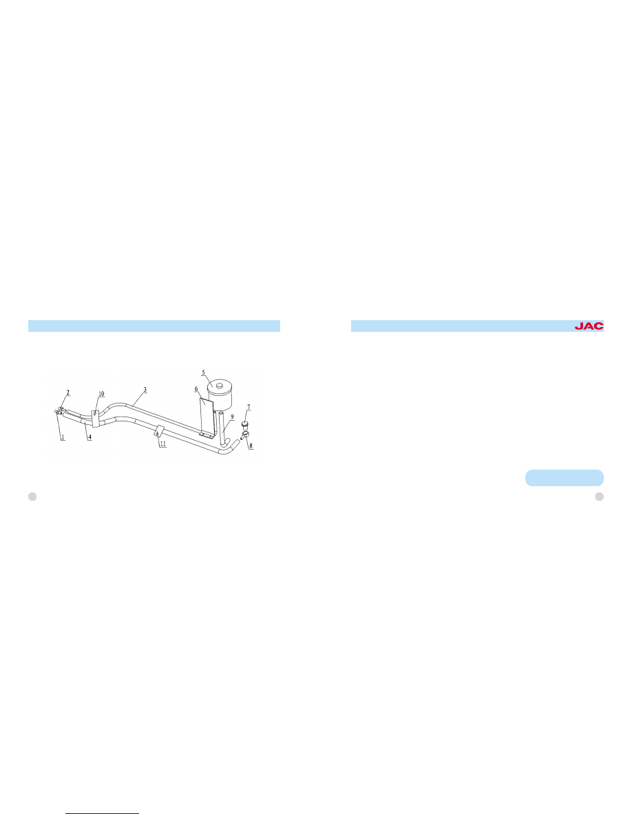
1. steering gear fuel inlet nipple
2. steering gear fuel outlet nipple
3. power-steering fuel return flexible pipe
4. power-steering flexible pipe assembly

5. power-steering oil container assembly
6. power-steering oil container supporter
7. oil pump outlet bolt
8. oil pump inlet nipple

9. oil pump inlet flexible pipe
10. hose clamp
11. wire clip

Steering system

The steering system of this series of
truck is power steering system.

Power steering system
It is composed of steering control
mechanism, transmission mecha鄄

nism, unitized power -steering gear,
power steering pump and power -
steering pipeline etc.

46

OWNER爷S MANUAL for

HFC1061,HFC1063,HFC1083

series trucks

Power steering system adopts driv鄄
er's physical power and engine
power as steering energy. It can be
steering solely driven by driver if the
boost device do not work. So com鄄
pared with common mechanical
steering system, power-steering sys鄄
tem is acuter and safer, easing fa鄄
tigue of driver to a large extent.
Checking procedures of power -steer鄄
ing system's working state:
1. Put front wheel on the steering
platform.
2. Turn the steering wheel to left and
right pole to check if the steering
wheel has phenomenon of getting
stuck and getting impeded.
3. Check free play of steering wheel
when engine runs in idle speed. Free

play of steering wheel is 15-35mm.
Rotate adjusting screw clockwise to
decrease the free play, while rotate
anti-clockwise to increase it.
4. Rotational force of steering wheel
is around 19.6N when engine runs in
idle speed.
5. Check working condition of all of
the switches including starter switch,
rain wiper switch, exhaust brake
switch, horn switch and combination
switch.
Procedures of air exhausting in power
steering system:
1. Add steering oil (specified oil ) in鄄
to oil tank.
2. After standing up the front axle by
using jack, use prop stand to sup鄄
port frame.

3. Rotate steering wheel to left and
right pole for several times.
4. Check oil level of power-steering
oil tank, add steering oil if there is
not enough oil. Check whether oil lev鄄
el is in normal temperature scope.
5. Start engine, rotate steering wheel
to left and right pole for several times
if engine runs in idle speed. During
the process of exhausting air, add
steering oil constantly into oil tank to
ensure power-steering oil tank full.
6. Rotate steering wheel to make
wheel confront forward.
7. After switching off engine, check
oil level and add steering oil if neces鄄
sary.

47

Note: check whether steering oil is
in high temperature scope, if stee-

Check and maintenance:
1. Replace steering gear oil in time
and clean &replace filtering screen in
oil tank when a new truck runs for
3000 -4000km and runs every 5000
km afterwards.
2. Check oil volume and oil quality in
oil cylinder often, adding or replacing
if oil goes bad.
3. Pay attention to the mark of oil inlet
and outlet in pipeline connecting
when strip and re-assemble steering
mechanism to make sure it is con鄄
nected right. After connecting pipe-

line, check it to prevent air from enter鄄
ing into oil outlet pipeline of oil pump.
Start engine to make it run in idle
speed and add oil into oil tank. If the
system has not been poured enough
oil, rotate steering wheel repeatedly
left and right to extreme position and
add oil into oil tank at the same time
until oil level in oil tank doesn't drop
and has no air bubble. Add oil until oil
level is marked. When adding, check
oil tank and pipeline connector of
steering system to make sure them
clean, having no impurity. Specific
connect are as follows:

Connect oil outlet to oil inlet of

steering oil pump.

Connect oil return hole of steering

gear to oil return hole of oil tank.

4. When power -steering system
doesn't work, driver can use hand de鄄
pending on mechanical steering part.
However, using mechanical steering
only for a long time is forbidden.
5. Power -steering system has a
function of spot turn. Be sure to
avoid rotating steering wheel to ex鄄
treme position to prevent decreasing
life of components.
6. Add liquid oil according to pre鄄
scription. If surrounding temperature
is 0益 above, use L -HM464# anti鄄
wear hydraulic oil.If surrounding tem鄄
perature is 0益 below, use L-LM32#
antiwear hydraulic oil or 8# hydraulic
automatic steering oil. (mixture of
different oil type is forbidden). Use
DEXRON域type hydraulic oil for im鄄

48

OWNER爷S MANUAL for

HFC1061,HFC1063,HFC1083

series trucks

ring oil has been cooled, check
whether it is at normal temperature.
If finding problem, repeat step4
and step5. If the problem still ex鄄
ists, repair power-steering pump.

49

port power -engine steering gear or
steering pump. ( referring to Ameri鄄
can General

Motors

Corporation

standard )
Using and maintenance:
1. Using of power -engine steering
system

Rotating steering wheel to extreme

position for 5s is forbidden.

Continuing rotating steering wheel

after rotating to dead space is forbid鄄
den.

Rotating steering wheel when

wheels stand still is forbidden.

Rotating steering wheel for more

than 90r/min is forbidden.
2. Maintenance of power -engine
steering system
Carry out principle of vehicle mainte鄄

nance that is " preventing mainly,
check and measure periodically and
maintain obligatorily ". Obey Ministry
of Communication standard JT/
T201-95
" Norm of vehicle maintenance craft "
and Ministry of city Construction
standard CJ17-86 " city bus repair in
technique condition ".

Make inspection and adjustment

on steering system before driving,
during driving and after driving to
guarantee driving safety.

Class-one maintenance ( 2000-

3000km)

Add lubrication periodically into every

lubricating point and add power-steering
oil in time when power -steering system
oil is not enough.

Make sure cross shaft and steering

cross and straight pull rod rotate flexible
and tight

Check the tightening condition of every

connection point to make sure them tight.

Check connection point of pipeline to

make sure there is no leakage.

Class -two maintenance 渊10000要

15000km冤

Replace power-steering oil.

Clean filtering screen of power-steer鄄

ing oil tank.

Check slack of steering-wheel and ad鄄

just it to allowable value.

Make flaw detection on front shaft, ball

pin, steering knuckle , steering knuckle
arm, steering drop arm and steering gear
support frame.

Disassemble cross and straight pull

rod, clean and check each component to
make sure there is no crack on the body
of cross and straight pull rod as well as
making sure screw thread on two ends
not worn and limit wearing scope to 2mm
for cotter pin hole of cross and straight
pull rod , 0.5mm for spheri cal surface.
Also make sure spring can work well.

Referring to JT 辕 T 201要95 for oth er

non-mentioned part.

For vehicle mounted steering drop

arm limit bolt :

Make sure limiting reliability

Do instant replacement if finding dam鄄

age on steering gear support frame
check arm.

Check connection bolt connecting

steering gear and support frame as well
as checking support frame and vehicle
frame to make sure them tight.

When doing left and right steering,

steering straight pull rod should not be in鄄
terfered in steering gear support frame
limit arm. If it results in the damage of
straight, replace it in time.

Braking system

Braking systems of trucks of this se鄄
ries are: parking brake system(center
drum) and running brake system (air
brake, hydraulic brake)

Running brake system

Air brake
1. Brief description of this system:
Compared with hydraulic brake, air
brake can bring greater braking
force under the condition that force
on the pedal is not great and the
pedal stroke is not long; at the same
time, dual-circuit air-pressure driv鄄
ing braking device is equipped to
front and rear wheel separately, so
the braking is safe, reliable, labor -
saving, and more effective; even if
one of the brakes does not work, the
vehicle can still brake safely.

50

OWNER爷S MANUAL for

HFC1061,HFC1063,HFC1083

series trucks

Interface for air inlet

Interface for low fressure alarming

Interface for clutch booster

1.air compressor
2.front brake cha-mber
3.front cavity on main gas cylinder
4.rear cavity on main gas cylinder
5.safety valve

6.pressure control valve
7.barometer
8.brake valve
9.additional gas cylinder;
10.one-way valve

11.front quick-release valve
12.rear brake valve
13.rear quick-release valve

51

2. Structure and theory (referring to the following diagram).

Brake pipeline is arranged as fol鄄
lows: compressed air produced by
air compressor 1 comes into the
main air reservoir 3 (namely wet air
reservoir); and then the air is separat鄄
ed into two and come into the front
chamber 9 of the auxiliary air reser鄄
voir and the rear chamber 4 of the
main air reservoir, the front chamber
9 of the auxiliary air reservoir and the
rear chamber 4 of the main air
reservoir. Compressed air in the front
chamber 9 of the auxiliary air reser鄄
voir and the rear chamber 4 of the
main air reservoir come into upper
and lower chambers of brake valve
8, and then the air is transported
separately to rear brake chamber 12
and front brake chamber 2. Check

valves 10 installed on ends of the air
inlet pipes of the front chamber 9 of
the auxiliary air reservoir and the rear
chamber 4 of the main air reservoir in
case that compressed air in the air
reservoir flows backwards. There are
interfaces for air pressure gauge 7
and pressure -adjusting valve 6.
When air pressure reaches 0.74 -
0.84Mpa, compressed air props up
valve of the pressure -adjusting
valve, and comes into upper cover of
the air compressor to make air inlet
valve open and the air compressor
idles. When brake valve 8 is de鄄
pressed, front and rear brake cham鄄
ber 2 and 12 operate at the same
time, which makes front and rear
brakes operate. When the brake ped鄄

al is released, compressed air in
front and rear brake chambers go in鄄
to the atmosphere by front and rear
air-deflating valves 11 and 13.

52

OWNER爷S MANUAL for

HFC1061,HFC1063,HFC1083

series trucks

1. return spring locating pin
2. roller shaft-brake shoe
3. roller-brake shoe
4. gripping ring -brake shoe roller
shaft
5/18. front brake shoe with liner as鄄
sembly
6/19. front brake friction plate
7. brake cam
8. front brake baseboard with liner
assembly
9. front brake dust cap

10. hex bolt
11. front brake air chamber support
frame with liner assembly
12. front left brake air chamber as鄄
sembly
13. hex bolt
14. front brake adjusting arm as鄄
sembly
15. shoe shaft fixed bolt
16. front brake shoe-shoe shaft;
17. front and rear brake shoe
shaft-liner; 18. return spring

Brake assembly
The function of brake is to utilize
power produced by friction between
brake drum and brake shoe slice to

absorb kinetic energy of vehicle to
decelerate or stop the vehicle. Front
and rear brakes of this brake system
adopt imbalanced structure and are

mainly composed of brake chamber,
brake arm and brake

53


Content   ..  1234  1235  1236  1237   ..