Isuzu N-Series. Manual - part 1142


  Index      Isuzu     Isuzu N-Series - service repair manual


Search            


Content   ..  1140  1141  1142  1143   ..


Isuzu N-Series. Manual - part 1142


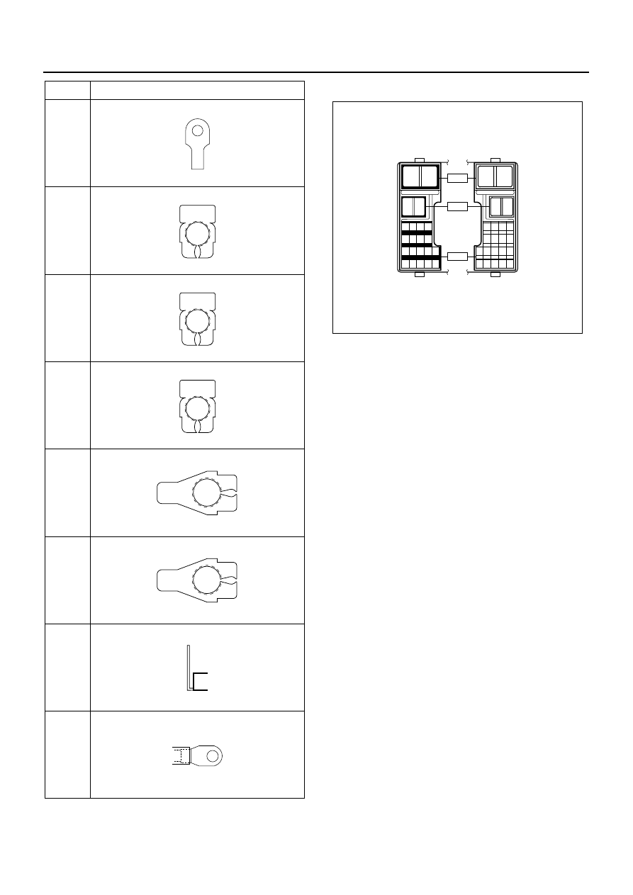
8-280 CAB AND CHASSIS ELECTRICAL

H-6, H-7

P-1

(12V)

P-2

P-1

(24V)

P-4

P-2

(24V)

P-3

P-5

(12V)

P-5

(24V)

No.

Connector Face

000-003

000-004

000-004

000-004

000-006

000-006

000-007

000-002

1

2

1

2

1 2 3 4

5 6 7 8

9 10 11 12 13

14 15 16 17 18

2

1

2

1

4 3 2 1

8 7 6 5

13 12 11 10 9

18 17 16 15 14

H - 6

H - 7

H - 8

N8A5489E

CAB AND CHASSIS ELECTRICAL 8-281

Diagnosis

Cigar Lighter Does Not Heat Sufficiently

The Cigar Lighter Does Not Spring Out After Being Heated

• IS FUSE  F-15  (15A) NORMAL?

NO

• REMOVE THE CIGAR LIGHTER

• SET THE STARTER SWITCH TO EITHER "ACC" OR "ON"

POSITION

• IS THE BATTERY VOLTAGE APPLIED BETWEEN THE

BIMETAL AT THE CENTER OF THE CASE AND OUTER
OF THE CASE?

REPLACE THE FUSE

YES

• IS  B-7  GROUNDED SECURELY?

YES

NO

GROUND IT SECURELY

YES

NO

REPAIR A POOR CONNECTION AT THE
CONNECTORS OR AN OPEN CIRCUIT BETWEEN
FUSE  F-15  (15A) AND 1  B-44 

• SET THE STARTER SWITCH TO EITHER "ACC" OR "ON"

• IS THE BATTERY VOLTAGE APPLIED BETWEEN  B-7

AND GROUND?

REPLACE THE CIGAR LIGHTER ASSEMBLY

YES

REPAIR A POOR CONNECTION AT THE
CONNECTORS OR AN OPEN CIRCUIT BETWEEN 1 

B-45  AND  B-7 

NO

N8A0285E

• IS THE FORM OF CIGAR LIGHTER NORMAL?

NO

REPLACE THE CIGAR LIGHTER ASSEMBLY
(INCLUDE OUTER CASE)

REPLACE THE CIGAR LIGHTER

YES

N8A0286E

8-282 CAB AND CHASSIS ELECTRICAL

Starter Switch

Refer to “START AND CHARGING” in this section.

Radio

Removal
Preparation:
Disconnect the battery ground cable.

1. Center Cluster

1) Pull it to remove. Pry off three clips by the tip of

screwdriver.

2) Remove the cigar lighter power source and its

illumination connector.

Notice:
To remove the center cluster, do not force to pry off
three clips at upper portion of the center cluster.

2. Radio

1) Remove the two radio fixing screws.
2) Disconnect the connector and feeder plug.

Installation
To install, follow the removal steps in the reverse order.

Antenna

Inspection
The metal A is connected to the pole D at the top of the
antenna through the core of the feeder.
The metal B is fitted in the feeder shielding the core, and
grounded at the screw C to avoid the core hampered by
noise.
Defective grounding would cause noise.

Legend

1. Center Cluster

N8A5337E

Legend

1. Radio

N8A5338E

N8A0289E

CAB AND CHASSIS ELECTRICAL 8-283

In checking, measure the following three points with the
circuit tester in the range of “resistance x 1 (

Ω).”

Between A and B
No continuity (No reading at the indicator) 

Normal
Continuity (A bite in the feeder. The core grounded) 

Lower reception
Between B and C
Continuity (Indicator reading: 0

Ω) → Normal

No continuity (Shielded core disconnected or defective
grounding at the screw 

→ Hampered by noise)

Between A and D
Continuity or no continuity
There are some antenna feeders and relay feeders with
a condenser built in their connections.
Measuring resistance between the two points does not
result in correct judgment. Connect temporarily another
normal antenna to the radio and check to see if its re-
ception is audible. Most antenna now available are slide
type. Rust at the screw C and the cab panel where
grounded would lead no continuity, followed by lower re-
ception.
Keep this portion clean to avoid rust.
Removal
Preparation:
Disconnect the battery ground cable.

1. Antenna

1) Disconnect the joint connector.
2) Remove the upper and lower side antenna

bracket.

3) Pull out the antenna feeder.

Notice:
For easier fitting, tie the lead wire to the end of the an-
tenna feeder in advance.

Installation
To install, follow the removal steps in the reverse order.

Speaker

Inspection

1. With the circuit tester set to the range of 

× 1 (Ω),

connect the circuit tester probes (red and black) to
the (+) and (

−) terminals of the speaker.

2. When the speaker is normal, a low buzzing sound

is heard.

3. When the speaker is defective, no sound is heard.

However, the distortion or chattering of the sound
cannot be identified.
When the speaker is installed to the vehicle, dis-
connect the connectors before checking. 
When no sound is heard, the following are consid-
ered as the cause.

• The speaker wiring is disconnected at the speaker

terminals.

• The speaker body is defective.
• There is an open circuit somewhere in the speaker

harness on the vehicle side.

• The speaker harness on the vehicle side is ground-

ed or caught up.

Legend

1. Antenna

N8A5340E


Content   ..  1140  1141  1142  1143   ..