Content .. 1138 1139 1140 1141 ..
Isuzu N-Series. Manual - part 1140
8-272 CAB AND CHASSIS ELECTRICAL
Removal
Preparation:
Disconnect the battery ground cable.
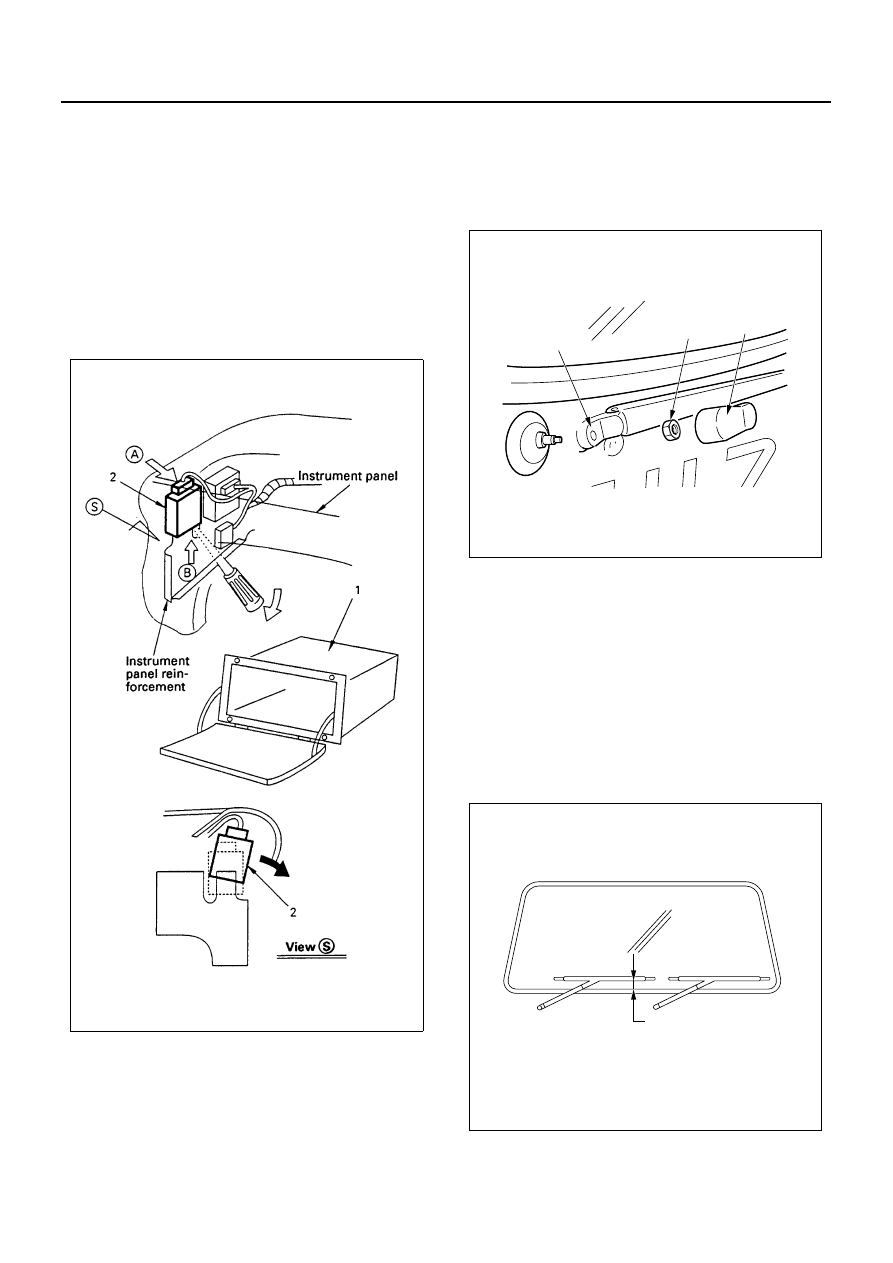
1. Glove Box
Open the lid and remove the four screws.
2. Intermittent Relay
1) Press A position with your finger and pry up B
position with the tip of a screw-driver.
2) When the relay moves up by about 2/3 of its
size, tilt and take off the relay to avoid interfer-
ence with the instrument panel.
3) Disconnect the connector.
Installation
To install, follow the removal steps in the reverse order.
Windshield Wiper Arm & Blade
Removal
1. Cover
2. Wiper Arm Nut
3. Wiper Arm & Blade
Installation
To install, follow the removal steps in the reverse order,
noting the following points.
1. Before installing the wiper arm & blade to the shaft,
confirm that the motor stops at the auto-stop posi-
tion.
2. Set the wiper arm & blade so that the tips of both
blades are positioned as shown in the illustration.
3. Tighten the wiper arm nut to the specified torque.
Tighten:
Wiper arm nut to 17 N
⋅m (170 kg⋅cm/147 lb⋅in)
N8A5317E
3
2
1
N8A5318E
Approx. 45mm(STD Cab)
Approx. 70mm(Wide Cab)
N8A5319E