Isuzu N-Series. Manual - part 1139


  Index      Isuzu     Isuzu N-Series - service repair manual


Search            


Content   ..  1137  1138  1139  1140   ..


Isuzu N-Series. Manual - part 1139


8-268 CAB AND CHASSIS ELECTRICAL

Starter Switch

Refer to “START AND CHARGING” in this section.

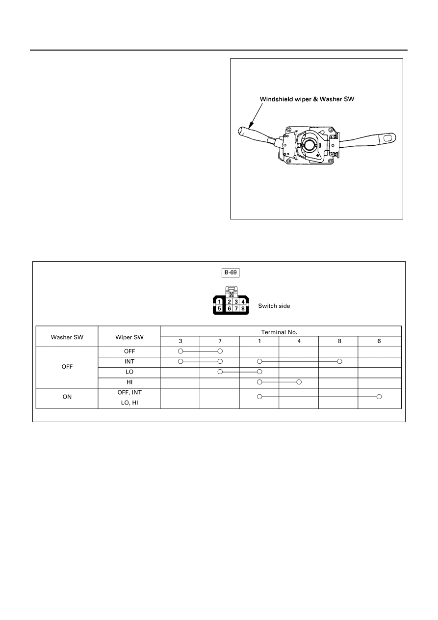
Windshield Wiper & Washer Switch

With the starter switch on, the windshield wiper and
washer switch controls the start and stop operation as
well as the change of operating speeds.
Both the windshield washer motor and the wiper
motor jointly operate while the washer button is
pushed.

Inspection
Check the continuity between the connector terminals of the switch.
Repair or replace the switch when the result of inspection is found abnormal.

Removal and Inspection
Refer to “HEADLIGHT, FOG LIGHT AND CORNERING
LIGHT” in this section.

N8A5310E

N8A5311E

CAB AND CHASSIS ELECTRICAL 8-269

Windshield Wiper Motor

Inspection

1. Operation in low speed

With the motor connector terminal 2 

 connect-

ed to the battery (+) terminal and the connector 1

 to the (

−) terminal, check to see if the motor

rotates in low speed.

2. Operation in high speed

With the motor connector terminal 3 

 connect-

ed to the battery (+) terminal and the connector 1

 to the (

−) terminal, check to see if the motor

rotates in low speed.

3. Stop operation

After stopping the windshield wiper in the position
on the way by confirming the operation at the low
speed in item No. 1.
When the connectors 2 

 and 5 

 are con-

nected, while connecting the motor connector ter-
minal 4 

 to the battery (+) terminal, check to

see, if the motor rotates at low speed and stops at
the auto-stop position.
Repair or replace the motor when the results of the
above inspections are found abnormal.

Removal
Preparation:
Disconnect the battery ground cable.

1. Glove Box

Refer to “INSTRUMENT PANEL” of section 2.

2. Windshield Wiper Motor

1) Disconnect the connector.
2) Remove four screws.
3) Remove the ball joint between crank arm and

wiper link.

Installation
To install, follow the removal steps in the reverse order,
noting the following points.

• Windshield Wiper Motor

When the crank arm is removed from the wind-
shield wiper motor, tighten the motor shaft nut with
the specified torque.

Tighten:
Shaft nut to 17 N

⋅m (170 kg⋅cm/147 lb⋅in) 

• Temporarily fit the motor by using one of the four

wiper motor fixing screws.

• Put the crank arm ball joint in the wiper link hole

and fix them together while pulling the wiper link.

N8A0263E

B-11

B-11

B-11

B-11

B-11

B-11

B-11

N8A5313E

8-270 CAB AND CHASSIS ELECTRICAL

Windshield Washer Motor

Inspection
With the battery (+) terminal connected to the washer
motor connector terminal 1 

 and the (

−) terminal to

the connector 2 

, check to see if the cleaning fluid

pushes out.
Replace the tank/motor when the result of inspection is
found abnormal.

Removal
Preparation:
Disconnect the battery ground cable.

1. Instrument Panel Under Cover

Refer to “INSTRUMENT PANEL” of section 2.

2. Washer Tank

1) Disconnect the washer motor connector.
2) Disconnect the washer hose.
3) Remove three fixing screws.

3. Clip Band
4. Windshield Washer Motor

Hold the motor and pull it out from the washer tank.

Installation
To install, follow the removal steps in the reverse order.

B-8

B-8

1

2

B-8

N8A0265E

N8A5315E

CAB AND CHASSIS ELECTRICAL 8-271

Intermittent Relay

Circuit Diagram

N8A0267E


Content   ..  1137  1138  1139  1140   ..