Isuzu N-Series. Manual - part 1090


  Index      Isuzu     Isuzu N-Series - service repair manual


Search            


Content   ..  1088  1089  1090  1091   ..


Isuzu N-Series. Manual - part 1090


8-72 CAB AND CHASSIS ELECTRICAL

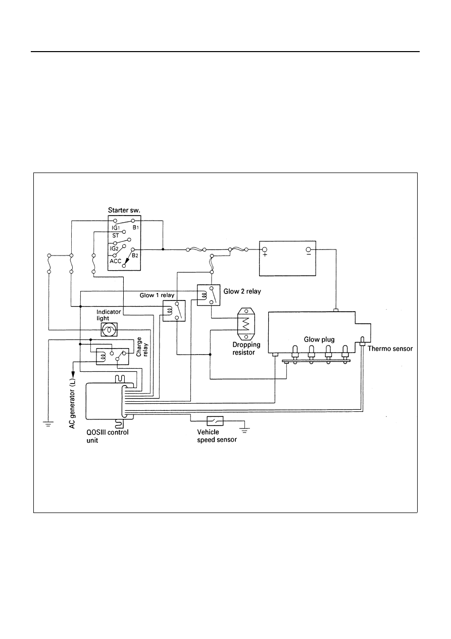
QOS (Quick On Start) III System (4JG2 Engine Model)

General Description

The system consists of starter switch, QOS III control unit, glow relay, charge relay, fuel cut solenoid, dropping resis-
tor, thermo sensor, glow plug, engine speed sensor, accel switch and glow indicator light.
Perceiving the engine coolant temperature when the engine started, the thermo sensor varies the glowing time to al-
ways get the most suitable condition for engine starting.
The indicator timer starts to operate as soon as the starter switch turns to “ON” position, and the indicator light turns
on and keeps lit until the glow plugs have been heated to the level ready for the engine starting, when the indicator
light is off.
For details, refer to “PREHEATING SYSTEM”.

System Circuit

N8A5078E

CAB AND CHASSIS ELECTRICAL 8-73

Parts Location

N8A5079E

8-74 CAB AND CHASSIS ELECTRICAL

Circuit Diagram

NHR69

B-10

B-10

B

ST

ACC

ON

B-67

B-67

B-67

H-7

B-10

B-10

B-51

B-51

B-10

B-10

B-10

X-19

X-19

X-19

X-19

H-8

H-8

B-10

X-11

B-10

X-20

X-20

X-20

X-20

E-3

E-16

H-5

H-14

E-16

H-14

H-5

H-5

X-11

B-7

B-10

J-60

J-60

P-1

P-2

P-5

2

1

3

4

22

2

3

4

5

2

1

2

5

3

4

18

3

5

12

1

5

2

3

1

4

61

3

8

6

11

10

4

1

40

15

1

2

8

37

5

9

FRAME

FL-1  100A

MAIN

FL-2  50A

KEY SW

FL-3  60A

GLOW

5B/L

3W/B

STARTER SWITCH

3B/Y

3B/W

F-22   10A

STARTER

F-16  10A

METER

0.5B/W

0.5B/Y

0.5B/W

0.3O/L

0.5B/Y

RELAY; STARTER (4)

GLOW INDICATOR LIGHT (METER)

METER B-52  (3)

0.5W/L

0.5W/L

0.85W/L

GENERATOR (L)

E-18

(1)

0.85W

F-18  15A

GENERATOR

3B/Y

RELAY; CHARGE

METER

B-52

0.5GR

0.5GR/B

THERMO SENSOR (GLOW)

0.3B/L

0.3B/R

1.25B

HEADLIGHT BRACKET (LH)

GLOW PLUG

RELAY; GLOW 1

RELAY; GLOW 2

5B/R

5B/Y

5B/L

0.5B/Y

5B/L

0.5B/Y

5B/Y

QOS III CONTROL UNIT

0.3W

3B

0.3B

0.3B

DROPPING RESISTOR

X-11

X-11

X-11

0.5GR

0.5GR/B

0.5B/L

2L

FUSE BLOCK

(2)

N8A5080E

CAB AND CHASSIS ELECTRICAL 8-75

Connector List

No.

Connector Face

B-10

B-17

X-11

B-51

B-67

B-67

B-75

E-2

013-001

1

2

3

7

8

9

4

5

6

11

12

13

10

004-004

1

2

3

4

005-001

1

3

2

4

5

014-001

1 2 3 4 5 6 7 8

9 1011121314

004-001

1

2

3

4

004-002

2
4

1
3

005-002

4

3

1

5

2

002-005

1

2

E-2

E-3

E-16

E-16

H-14

H-14

X-19

X-20

No.

Connector Face

002-006

1

2

000-009

002-009

1

2

002-010

1

2

016-003

1

2

3

4

5

6

7

8

9

11 12 13 14

15

16

10

016-004

4

3

2

1

9

8

7

6

5

13 12 11 10

16

15

14

005-003

1

2

3

5

4

005-003

1

2

3

5

4


Content   ..  1088  1089  1090  1091   ..