Isuzu N-Series. Manual - part 1053


  Index      Isuzu     Isuzu N-Series - service repair manual


Search            


Content   ..  1051  1052  1053  1054   ..


Isuzu N-Series. Manual - part 1053


CAB AND CHASSIS ELECTRICAL 8-317
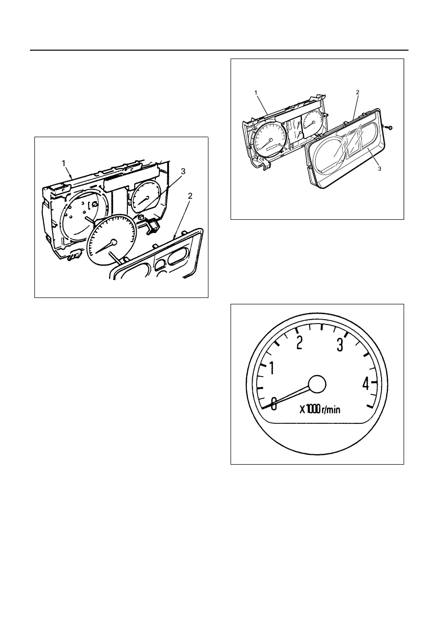
• Except 4HK1-TC

1. Meter Assembly

Refer to “METER ASSEMBLY” in this section.

2. Meter Glass

Remove it by pushing the catches with your finger.

3. Speedometer

Remove four screws securing the meter at the
back side.

• For 4HK1-TC

1. Remove the meter assembly/speedometer (1).

Notice:
Speedometer cannot be removed as a single unit since
it is integrated into the meter assembly.

• Refer to “Meter Assembly” in this section.

2. Remove the meter plate (2) and meter glass (3).

• Remove the two installing screws on the meter

surface.

• Remove the meter plate by pushing the catch-

es with your finger.

Installation
To install, follow the removal steps in the reverse order.

Tachometer

The tachometer is made up of the cross coil type amme-
ter (movement) that displays indications, and the drive
circuit (printed board) that makes exchange between
the pulse signals and the current.

On-vehicle Service Inspection

1. Set up the tune-up tester to the engine.
2. Start the engine and compare the readings dis-

played by the tachometer and the tester.
When the difference between these two readings
differs largely from the specified value, replace it
with a correct one.

Notice:
Since the meter display permissible levels above are
specifications solely for the meter, they are to be used
as reference values when conducting on-vehicle inspec-
tion.

N8A0333E

N8A0485E

N8A0334E

8-318 CAB AND CHASSIS ELECTRICAL

Except 4HK1-TC

For 4HK1-TC

Individual Inspection
Remove the tachometer from the meter assembly and
measure the resistance value and the current consump-
tion between each terminals.
Replace the tachometer when the result of inspection is
found abnormal.

1. Resistance value
Use the analog type circuit tester. (Range: 1K)
For 12 Volt tachometer

For 24 Volt tachometer

2. Current value
Use the analog type circuit tester.
Since the current consumption fluctuates as the power
voltage varies, check to be sure that the voltage applied
is 12

±1 V or 24±1 V.

Removal
Preparation:
Disconnect the battery ground cable.

• Except 4HK1-TC

1. Meter Assembly

Refer to “METER ASSEMBLY” in this section.

2. Meter Glass

Remove it by pushing the catches with your finger.

3. Tachometer

Remove three screws securing the meter at the
back side.

Tester display speed

Meter display 

permissible level

500

400 — 500

1000

800 — 1050

2000

1800 — 2050

3000

2800 — 3050

4000

3800 — 4050

Tester display speed

Meter display 

permissible level

750

700 — 800

2000

1900 — 2150

3000

2950 — 3200

4000

3950 — 4200

N8A0336E

Terminal

symbol

Tester terminal

Red 

(+)

Black 

(

−)

Black 

(

−)

Red 

(+)

IGN — GND

IGN

GND

IGN

GND

30

±5 kΩ

PIN — GND

PIN

GND

PIN

GND

33

±5 kΩ

500 — 1000 k

Terminal

symbol

Tester terminal

Red 

(+)

Black 

(

−)

Black 

(

−)

Red 

(+)

IGN — GND

IGN

GND

IGN

GND

30

±5 kΩ

PIN — GND

PIN

GND

PIN

GND

33

±5 kΩ

500 — 1000 k

Voltage

Connecting 

terminal

Current 

consumption

Remarks

12Volt 

IGN — GND

12

±1 V

(when 12

±1 V 

applied)

No signal 

input

24Volt 

24

±1 V

(when 24

±1 V 

applied)

No signal 

input

CAB AND CHASSIS ELECTRICAL 8-319

• For 4HK1-TC

1. Remove the meter assembly/tachometer (1).

Notice:
Tachometer cannot be removed as a single unit since it
is integrated into the meter assembly.

• Refer to “Meter Assembly” in this section.

2. Remove the meter plate (2) and meter glass (3).

• Remove the two installing screws on the meter

surface.

• Remove the meter plate by pushing the catch-

es with your finger.

Installation
To install, follow the removal steps in the reverse order.

Coolant Temperature Gauge

Circuit Diagram

Inspection
Remove the coolant temperature gauge from the meter
assembly, and measure the resistance value between
each terminal.
Replace the coolant temperature gauge when the result
of inspection is found abnormal.

N8A0337E

N8A0485E

+

IGN

GND

UNIT

Thermo unit

Engine coolant temperature gauge

-

N8A0338E

8-320 CAB AND CHASSIS ELECTRICAL

Removal
Preparation:
Disconnect the battery ground cable.

• Except 4HK1-TC

1. Meter Assembly

Refer to “METER ASSEMBLY” in this section.

2. Meter Glass

Remove it by pushing the catches with your finger.

3. Coolant Temperature Gauge

Remove six screws securing the meter at the back
side.

• For 4HK1-TC

1. Remove the meter assembly (1).

Notice:
Coolant temperature gauge and fuel gauge cannot be
removed as a single unit since they are integrated into
the meter assembly.

• Refer to “Meter Assembly” in this section.

2. Remove the meter plate (2) and meter glass (3).

• Remove the two installing screws on the meter

surface.

• Remove the meter plate by pushing the catch-

es with your finger.

Installation
To install, follow the removal steps in the reverse order.

Terminal symbol

Resistance value

IG — U

169 

Ω±10%

U — E

333 

Ω±10%

IG — E

242 

Ω±10%

N8A0339E

N8A0340E

N8A0485E


Content   ..  1051  1052  1053  1054   ..