Isuzu N-Series. Manual - part 1054


  Index      Isuzu     Isuzu N-Series - service repair manual


Search            


Content   ..  1052  1053  1054  1055   ..


Isuzu N-Series. Manual - part 1054


CAB AND CHASSIS ELECTRICAL 8-321
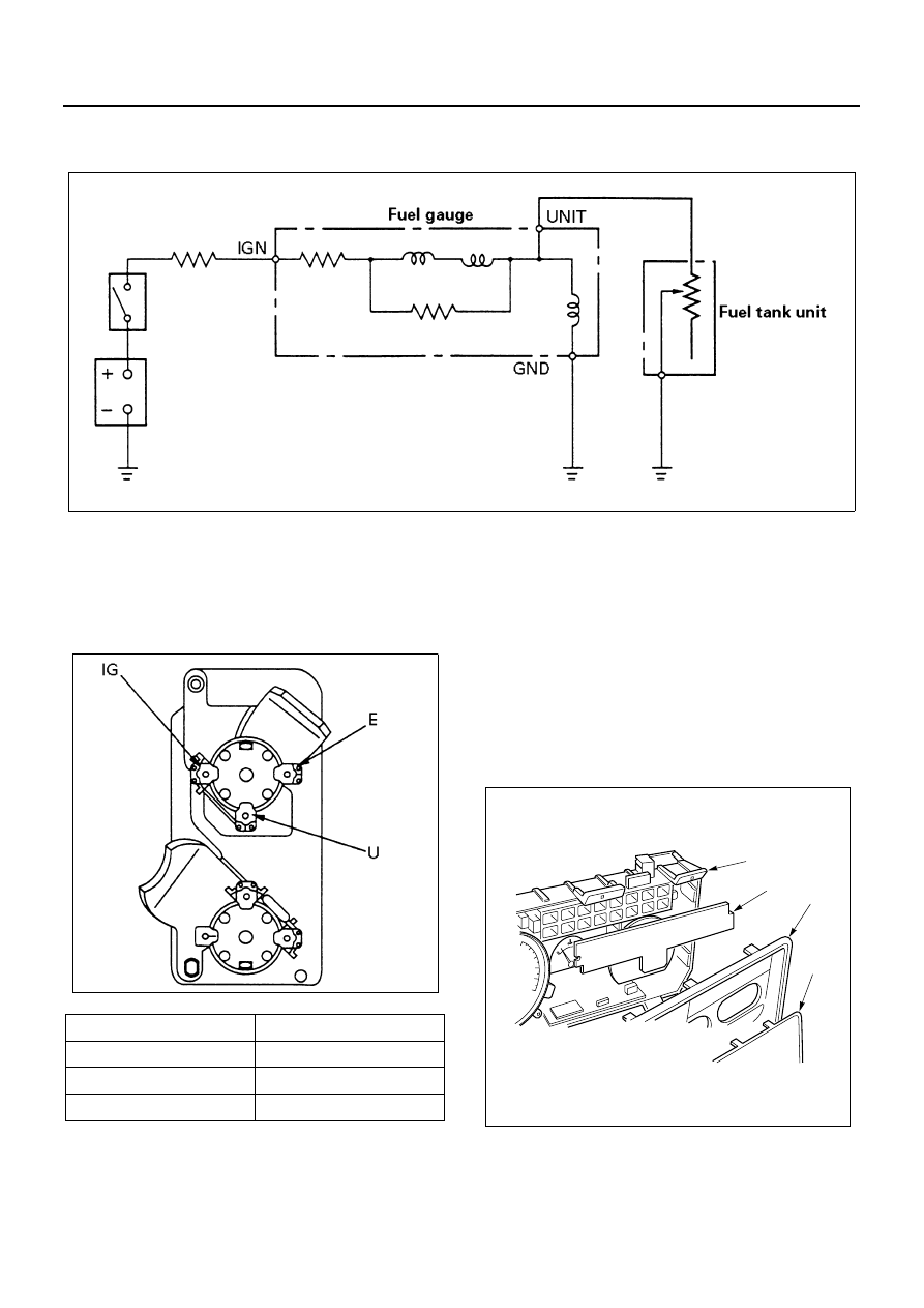
Fuel Gauge

Circuit Diagram

Inspection
Remove the fuel gauge from the meter assembly, and
measure the resistance value between each terminal.
Replace the meter when the result of inspection is found
abnormal.

Removal and Installation
Refer to the “COOLANT TEMPERATURE GAUGE” in
this section.

Warning Lens

Removal
Preparation:
Disconnect the battery ground cable.

1. Meter Assembly

Refer to “METER ASSEMBLY” in this section.

2. Meter Glass

Remove it by pushing the catches with your finger.

3. Meter Plate

Remove it by pushing the catches with your finger.

4. Warning Lens

N8A0341E

Terminal symbol

Resistance value

IG — U

108.1 

Ω±10%

U — E

103 

Ω±10%

IG — E

211.1 

Ω±10%

N8A0342E

3

2

1

4

N8A5404E

8-322 CAB AND CHASSIS ELECTRICAL

Installation
To install, follow the removal steps in the reverse order.

Warning Light Bulb, Indicator Light Bulb and Il-
lumination Light Bulb

Removal
Preparation:
Disconnect the battery ground cable.

1. Meter Assembly

Refer to “METER ASSEMBLY” in this section.

2. Socket and Bulb

Hold the bulb socket by hand and rotate it counter-
clockwise to remove them from the meter body.

3. Bulb

Pull out the bulb from the socket.

Installation
To install, follow the removal steps in the reverse order.

Vehicle Speed Sensor

The vehicle speed sensor is installed on the rear portion
of the transmission or transfer case.
The number of pulses generated is four pulses per one
rotation of the pinion shaft.

Inspection

1. Connect a resistance of 390 

Ω±5%, 2W between

connector terminal 1 

 and battery (+) terminal

and connect the connector terminal 2 

 to the

battery (

−) terminal.

Caution:
Be extremely careful not to connect the battery (+) ter-
minal to the connector 3 

.

This may damage the vehicle speed sensor.

2. Rotate the shaft of the vehicle speed sensor slowly

and measure the voltage between 3 

 and 2

 with a digital tester.

The voltage, with one rotation of shaft, fluctuates four
times in the following range: 10 to 14V 

↔ 24 or less.

Replace the sensor when the result of inspection is
found abnormal.

Legend

1. Meter Assembly
2. Meter Glass
3. Meter Plate
4. Warning Lens

N8A0344E

N8A0345E

J-32

J-32

J-32

J-32

J-32

CAB AND CHASSIS ELECTRICAL 8-323

Removal
Preparation:
Disconnect the battery ground cable.

1. Vehicle Speed Sensor

Disconnect the connector.

Installation

1. Tighten the vehicle speed sensor to the specified

torque.

Tighten:
Vehicle speed sensor to 25 N

⋅m (2.5 kg⋅m/18 lb⋅ft)

Caution:
Tightening must be made at the hexagonal part of the
sensor.

To tighten the connector itself would cause damage.

Thermo Unit

Inspection
The thermo unit is thermistor type and must be inspect-
ed under the conditions as shown below.

1. Put the deviation of the galvanometer to 0 by using

the variable resistor, switch the thermo unit off and
then measure the resistance of the resistor through
the bridge.
Confirm that the resistance is continuously variable
in any other points than those shown below.

2. Dip the thermo unit into 80 — 90

°C (176 — 194°F)

water and confirm that there is no bubble continu-
ously coming out of inside of the unit.
Replace the unit when the result of inspection is
found abnormal.

N8A0346E

Parking

brake drum

Connector

1

N8A0347E

Check condition

Temperature

50

°C

(112

°F)

115

°C

(239

°F)

7 V 55 

Ω 

Gauge

Resis-

tance value

(

Ω)

+33.6

−33.6
226.0

+1.71

−2.21

26.4

7 V 25 

Ω 

Gauge

+2.68

−3.68

24.3

N8A0348E

8-324 CAB AND CHASSIS ELECTRICAL

Oil Pressure Switch

Inspection
Check the continuity between the switch terminal and
the body ground with the starter switch is OFF position.
Replace the switch when the result of inspection is
found abnormal.

Circuit Inspection

1. Start the engine.
2. When disconnecting the oil pressure switch con-

nector then connecting the harness side connector
to the ground, check to see if the oil pressure warn-
ing light lights up. When the light will not light up,
check the circuit between the meter and the oil
pressure switch, and repair an open circuit if nec-
essary.

Fuel Tank Unit

The tank unit varies the internal resistance according to
the float position (fluid level) to operate the fuel meter
needle. Also available is the build-in switch type to warn
the driver of low fuel level (about 5 liters left in the tank)
by illuminating the fuel warning light.

Inspection
(Level Switch type of warn low fuel level)

1. Check the resistance between the connector termi-

nals 1 

 and 3 

 while shifting the float

from “E” to “F” point.

2. Check if the low fuel warning switch turns on and

off at the specified positions. If found defective, re-
place the fuel tank unit.

N8A5410E

N8A5411E

N8A5412E

J-28

J-28


Content   ..  1052  1053  1054  1055   ..