Isuzu N-Series. Manual - part 79
2-22 CAB AND FRAME
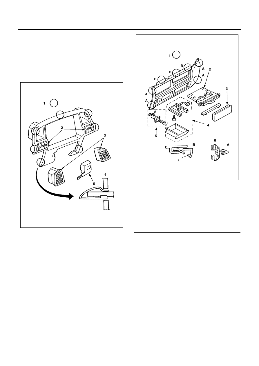
Removal
1. Meter cluster
• Pull the main unit toward you and remove the
clips at 7 positions. Remove each switch con-
nector. When switches are mounted on the
switch cover, remove the connectors.
• Remove the vent grille, switch cover and each
switch from the cluster proper.
2. Center cluster
• Pull the main unit toward you and remove the
clips A at 4 positions, clips B at 3 positions, ci-
gar lighter power source and ashtray lighting
connector. When an auto air conditioner is
mounted, remove the room sensor.
• Remove the drink holder, control unit cover (or
glove compartment), ashtray and cigar lighter
from the center cluster proper.
Caution:
Remove the clips B with a bladed screwdriver.
3. Glove box
• Open the lid and remove the 4 mounting
screws.
Then, remove the main unit.
• Remove the left and right stays, remove the 3
mounting screws, and remove the lid.
• Pull out the pin from the lid and remove the
spring and lever.
Caution:
The Instrument panel assembly of this item can be re-
moved without disassembling each of the parts of above
items 1 — 3.
Legend
1. Clip position
2. Switch
3. Vent grill
4. Clip section
5. Switch cover
N2A0039E
Legend
1. Clip position
2. Drink holder
3. Control unit cover
4. Ashtray
5. Cigar lighter
6. Clip section
7. Center cluster
N2A0040E