Isuzu N-Series. Manual - part 65


  Index      Isuzu     Isuzu N-Series - service repair manual


Search            


Content   ..  63  64  65  66   ..


Isuzu N-Series. Manual - part 65


1B-30 AIR CONDITIONING

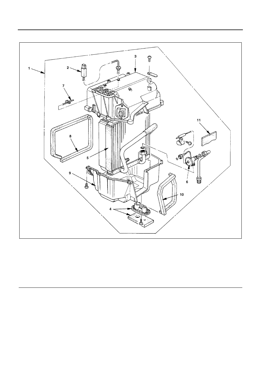
Evaporator Core / Expansion Valve (LHD Model)

Legend

1. Evaporator assembly

7. Thermo sensor

2. Electronic thermostat

8. Lining

3. Upper case

9. Lower case

4. Insulator and under cover

10. Lining

5. Evaporator core

11. Insulator

6. Expansion valve

N1A0088E

AIR CONDITIONING 1B-31

Removal

Preparation:
Disconnect the battery ground cable.
Discharge and recover refrigerant.

1. Evaporator Assembly

Refer to “EVAPORATOR ASSEMBLY” removal
procedure in this section.

2. Electronic Thermostat

• Remove the sensor fixing clip.
• Pull out the grommet from the upper case to re-

move the thermostat.

3. Upper Case

• Separate the upper and lower case.
• Slit the case parting face with a knife since the lin-

ing is separated.

4. Insulator and Under Cover
5. Evaporator Core

Pull up the core from the lower case.

6. Expansion Valve

• Tear off the insulator (1) carefully.
• Remove the sensor fixing clip.
• Use a back up wrench when disconnecting all re-

frigerant pipes, and remove the expansion valve
(2).

Installation

To install, follow the removal steps in the reverse order,
noting the following points:

1. O-rings cannot be reused. Always replace new

ones.

2. Be sure to apply new specified compressor oil to

the O-rings when connecting lines.

3. Be sure to install the expansion valve sensor and

the insulator on the place where it was before.

4. To install a new evaporator core, add 50cc (1.4

Imp. fl oz) of new specified compressor oil to a new
core and install the thermostat sensor to the evap-
orator core specified position with the clip where it
was before.

5. Tighten the refrigerant lines to the specified torque.

Tighten:

• Refrigerant line 1 to 10 N

⋅m (1.0 kg⋅m/7 lb⋅ft)

• Refrigerant line 2 to 15 N

⋅m (1.5 kg⋅m/11 lb⋅ft)

• Refrigerant line 3 to 20 N

⋅m (2.0 kg⋅m/14 lb⋅ft)

6. Apply an adhesive to parting face of lining when

assembling evaporator assembly.

7. The thermostat sensor (1) is installed on the core

with the clip (2) and it must not interfere with the
core.

N1A0089E

N1A0090E

N1A0091E

1B-32 AIR CONDITIONING

Evaporator Core / Expansion Valve (RHD Model)

Legend

1. Evaporator assembly

7. Evaporator core

2. Upper case

8. Pipe assembly

3. Lining

9. Lower case

4. Clip

10. Expansion valve

5. Amplifier & Thermistor

11. Insulator and cover

6. Thermo sensor

N1A0193E

AIR CONDITIONING 1B-33

Removal

Preparation:
Disconnect the battery ground cable.
Discharge and recover refrigerant.

1. Evaporator Assembly

Refer to “EVAPORATOR ASSEMBLY” removal
procedure in this section.

2. Amplifier & Thermistor

• Remove the sensor fixing clip.
• Pull out the grommet from the upper case to re-

move the thermostat.

3. Upper Case

• Separate the upper and lower case.
• Slit the case parting face with a knife since the lin-

ing is separated.

4. Insulator and Cover
5. Evaporator Core

Pull up the core from the lower case.

6. Expansion Valve

Take off two installation bolts and subsequently re-
move pipe assembly and expansion valve sequen-
tially.

Installation

To install, follow the removal steps in the reverse order,
noting the following points:

1. Tighten the expansion valve to the specified

torque.

Tighten:

Installation bolts to 5 N

⋅m (0.5 kg⋅m/3.7 lb⋅ft)

2. O-rings cannot be reused. Always replace new

ones.

3. Be sure to apply new specified compressor oil to

the O-rings when connecting lines.

4. To install a new evaporator core, add 50cc (1.4

Imp. fl oz) of new specified compressor oil to a new
core.

5. Apply an adhesive to parting face of lining when

assembling evaporator assembly.

6. Install the amplifier & thermistor sensor (2) surely

to the evaporator core specified position with the
clip (1) where it was before.

N1A0194E


Content   ..  63  64  65  66   ..