Isuzu N-Series. Manual - part 64


  Index      Isuzu     Isuzu N-Series - service repair manual


Search            


Content   ..  62  63  64  65   ..


Isuzu N-Series. Manual - part 64


1B-26 AIR CONDITIONING

3. Tighten the line to the specified torque.

Tighten:

Refrigerant Line to 6 N

⋅m (0.6 kg⋅m/4 lb⋅ft)

4. O-rings cannot be reused. Always replace with

new ones.

5. Be sure to apply new specified compressor oil to

the O-rings when connecting refrigerant line.

Pressure Switch

Removal

Preparation:
Disconnect the battery ground cable.
Discharge and recover refrigerant.

1. Pressure Switch Connector
2. Pressure Switch

• Turn the pressure switch counterlockwise to re-

move it.

• When removing the switch connected part, the

connecting part should immediately be plugged or
capped to prevent foreign matter from being mixed
into the line.

Installation

To install, follow the removal steps in the reverse order,
noting the following points:

1. O-ring cannot be reused. Always replace with a

new one.

2. Be sure to apply new specified compressor oil to

the O-ring when connecting pressure switch.

3. Tighten the pressure switch to the specified torque.

Tighten:

Pressure switch to 10 N

⋅m (1.0 kg⋅m/7.4 lb⋅ft)
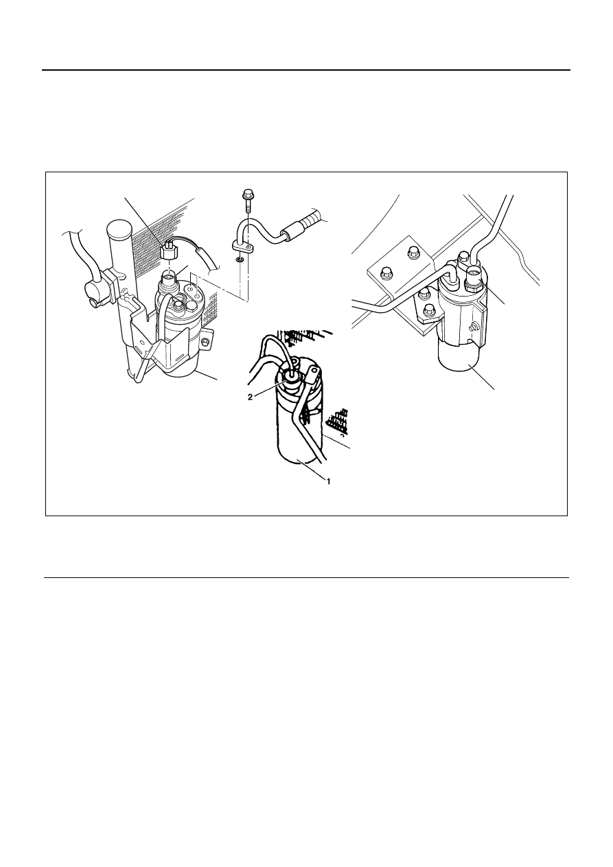
Legend

1. Receiver / drier

3. Triple pressure switch

2. Dual pressure switch

4. Pressure switch connector

4

1

2

3

1

for GCC

for Taiwan

for Australia

N1A0213E

AIR CONDITIONING 1B-27

Evaporator Assembly

Legend

1. Electronic thermostat connector

7. Drain hose

2. Temperature control cable

8. Under cover

3. Front grille

9. Evaporator assembly

4. Duct (NPR only)

10. Washer tank

5. Center cluster

11. Glove box

6. Refrigerant line

12. Resistor connector

12

11

10

8

7

9

5

4

7

2

6

N1A0083E

1B-28 AIR CONDITIONING

Removal

Preparation:
Disconnect the battery ground cable.
Discharge and recover refrigerant.

1. Glove Box

Open the glove box and remove the fixing screws.

2. Under Cover

While pulling the under cover (1) with care, remove
the clips (2) on the back side of the cover.

3. Washer Tank

• Remove the washer tank fixing three bolts (Upper:

two, Lower: one) and disconnect the connector.

• Do not disconnect the washer tank tube.

4. Center Cluster

• While pulling the cluster with care, remove the up-

per and back side clips (1) of the cluster.

• Disconnect the cigar lighter and illumination con-

nectors.

5. Temperature Control Cable

Disconnect the temperature control cable of the
control lever assembly from the heater unit.

6. Duct (NPR only)
7. Front Grille

After removing the grille, remove the grille fixing
clip (RH).

8. Refrigerant Line

• Use a back up wrench when disconnecting and re-

connecting the refrigerant line.

• When removing the refrigerant line connected part,

the connecting part should immediately be plugged
or capped to prevent foreign matter from being
mixed into the line.

9. Evaporator Assembly

• Disconnect the resistor and thermostat connec-

tors.

• Disconnect the drain hose.

N1A0026E

N1A0038E

Legend

1. Panel
2. Clip

N1A0086E

AIR CONDITIONING 1B-29

Installation

To install, follow the removal steps in the reverse order,
noting the following points:

1. To install a new evaporator assembly, add 50cc

(1.4 lmp fl oz) of new specified compressor oil to a
new core.

2. Tighten the refrigerant outlet line to the specified

torque.

Tighten:

Outlet line to 28 N

⋅m (2.8 kg⋅m/21 lb⋅ft)

3. Tighten the refrigerant inlet line to the specified

torque.

Tighten:

Inlet line to 15 N

⋅m (1.5 kg⋅m/11 lb⋅ft)

4. O-rings cannot be reused. Always replace with

new ones.

5. Be sure to apply new specified compressor oil to

the O-rings when connecting lines.

Legend

1. Evaporator
2. Grommet
3. Drain hose

N1A0087E


Content   ..  62  63  64  65   ..