Isuzu N-Series. Manual - part 57


  Index      Isuzu     Isuzu N-Series - service repair manual


Search            


Content   ..  55  56  57  58   ..


Isuzu N-Series. Manual - part 57


1A-22 HEATING AND VENTILATION

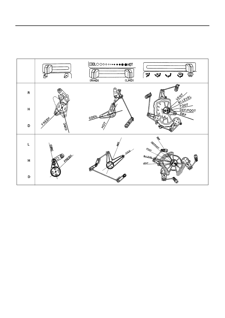
2) Connect the control cable at the “COLD”/“HOT”

position of the temperature control link of the
heater unit and fix it with the clip.

Air select control cable
1) Slide the control lever to the right (“DEFROST”

position).

2) Connect the control cable at the “DEFROST”

position of the mode control link of the heater
unit and fix it with the clip.

2. Check control cable operation.

N1A0041E

HEATING AND VENTILATION 1A-23

Control Panel Illumination Bulb

Removal

Preparation:
Disconnect the battery ground cable.

1. Control Panel Bezel

Refer to “CONTROL LEVER ASSEMBLY” removal
procedure.

2. Control Panel Illumination Bulb

Pull the bulb from the bulb socket.

Installation

To install, follow the removal steps in the reverse order.

Legend

1. Control panel bezel

3. Socket

2. Control panel illumination bulb

N1A0042E

1A-24 HEATING AND VENTILATION

Resistor

Removal

Preparation:
Disconnect the battery ground cable.

1. Under Cover

While pulling the under cover (1) with care, remove
the clips (2) on the backside of the cover.

2. Resistor Connector
3. Resistor

Installation

To install, follow the removal steps in the reverse order.

Legend

1. Under cover

3. Resistor

2. Resistor connector

4. Washer tank

N1A0043E

N1A0026E

AIR CONDITIONING 1B-1

HEATING AND AIR CONDITIONING

SECTION 1B

AIR CONDITIONING

Caution:

When fasteners are removed, always reinstall them at the same location from which they were removed. If a fastener
needs to be replaced, use the correct part number fastener for that application. If the correct part number fastener is
not available, a fastener of equal size and strength (or stronger) may be used.
Fasteners that are not reused, and those requiring thread locking compound, will be called out. The correct torque
values must be used when installing fasteners that require it. If the above conditions are not followed, parts or system
damage could result.

Contents

GENERAL DESCRIPTION ................................... 1B-2

Air Conditioning Refrigerant Cycle Construction ... 1B-2
Compressor ....................................................... 1B-3
Magnetic Clutch................................................. 1B-4
Condenser ......................................................... 1B-4
Receiver/Drier.................................................... 1B-4
Dual Pressure Switch (for GCC and Taiwan) .... 1B-5
Triple Pressure Switch (for Australia) ................ 1B-5
Evaporator ......................................................... 1B-6
Expansion Valve................................................ 1B-6
Electronic Thermostat........................................ 1B-7
Refrigerant Line ................................................. 1B-7
Service Charge Valves ...................................... 1B-7
Air Conditioning Parts........................................ 1B-8

ON-VEHICLE SERVICE ..................................... 1B-10

Precautions for Refrigerant -134a (R-134a) Air Condi-
tioning System ................................................. 1B-10
Precautions for Replacement or Repair of R-134a Air 
Conditioning Parts ........................................... 1B-12
Compressor ..................................................... 1B-20
New Compressor Installation........................... 1B-21
Condenser Assembly (Except 4HK1-TC Engine Mod-
el For Australia) ............................................... 1B-22
Condenser Assembly (4HK1-TC Engine Model For 
Australia) ......................................................... 1B-23
Receiver / Drier (Except 4HK1-TC Engine Model For 
Australia) ......................................................... 1B-24
Receiver / Drier (4HK1-TC Engine Model For Austra-
lia).................................................................... 1B-25
Pressure Switch............................................... 1B-26
Evaporator Assembly ...................................... 1B-27
Evaporator Core / Expansion Valve (LHD Model)... 1B-30
Evaporator Core / Expansion Valve (RHD Model) .. 1B-32
A/C Switch ....................................................... 1B-34
Refrigerant Line (Except 4HK1-TC Engine Model For 
Australia) ......................................................... 1B-36
Refrigerant Line (4HK1-TC Engine Model For Austra-
lia).................................................................... 1B-37


Content   ..  55  56  57  58   ..