Isuzu N-Series. Manual - part 58


  Index      Isuzu     Isuzu N-Series - service repair manual


Search            


Content   ..  56  57  58  59   ..


Isuzu N-Series. Manual - part 58


1B-2 AIR CONDITIONING

GENERAL DESCRIPTION

Caution:

This Vehicle is equipped with Refrigerant-134a (R-134a) air conditioning system. 
R-134a and A-12 systems require different types of lubricating oil. Components designed solely for use with one re-
frigerant and oil type must never be interchanged with components designed solely for use with another refrigerant
and oil type. Refer to “ON-VEHICLE SERVICE” for Precautions for R-134a Air Conditioning system in this section.

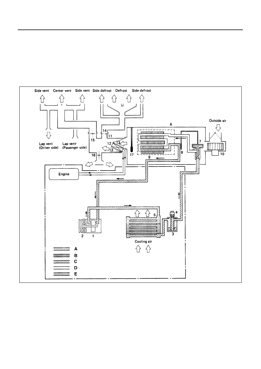
Air Conditioning Refrigerant Cycle Construction

N1A0045E

AIR CONDITIONING 1B-3

The refrigeration cycle includes the following four pro-
cesses as the refrigerant changes repeatedly from liquid
to gas and back to liquid while circulating.

Evaporation

The refrigerant is changed from a liquid to a gas inside
the evaporator. The refrigerant mist that enters the
evaporator vaporizes readily. The liquid refrigerant re-
moves the required quantity of heat (latent heat of va-
porization) from the air around the evaporator core
cooling fins and rapidly vaporizes.
Removing the heat cools the air, which is then radiated
from the fins and lowers the temperature of the air inside
the vehicle.
The refrigerant liquid sent from the expansion valve and
the vaporized refrigerant gas are both present inside the
evaporator and the liquid is converted to gas.
With this change from liquid to gas, the pressure inside
the evaporator must be kept low enough for vaporization
to occur at a lower temperature.
Because of that, the vaporized refrigerant is sucked into
the compressor.

Compression

The refrigerant is compressed by the compressor until it
is easily liquefied at normal temperature.
The vaporized refrigerant in the evaporator is sucked
into the compressor. This action maintains the refriger-
ant inside the evaporator at a low pressure so that it can
easily vaporize, even at low temperatures close to 0

°C

(32

°F).

Also, the refrigerant sucked into the compressor is com-
pressed inside the cylinder to increase the pressure and
temperature to values such that the refrigerant can eas-
ily liquefy at normal ambient temperatures.

Condensation

The refrigerant inside the condenser is cooled by the
outside air and changes from gas to liquid.

The high temperature, high pressure gas coming from
the compressor is cooled and liquefied by the condenser
with outside air and accumulated in the receiver/drier.
The heat radiated to the outside air by the high temper-
ature, high pressure gas in the compressor is called
heat of condensation. This is the total quantity of heat
(heat of vaporization) the refrigerant removes from the
vehicle interior via the evaporator and the work (calcu-
lated as the quantity of heat) performed for compres-
sion.

Expansion

The expansion valve lowers the pressure of the refriger-
ant liquid so that it can easily vaporize.
The process of lowering the pressure to encourage va-
porization before the liquefied refrigerant is sent to the
evaporator is called expansion. In addition, the expan-
sion valve controls the flow rate of the refrigerant liquid
while decreasing the pressure.
That is, the quantity of refrigerant liquid vaporized inside
the evaporator is determined by the quantity of heat
which must be removed at a prescribed vaporization
temperature. It is important that the quantity of refriger-
ant be controlled to exactly the right value.

Compressor

The compressor performs two main functions:
It compresses low-pressure and low-temperature refrig-
erant vapor from the evaporator into high-pressure and
high-temperature refrigerant vapor to the condenser.
And it pumps refrigerant and refrigerant oil through the
A/C system.
This vehicle is equipped with a swash plate type com-
pressor (DKS-15 D Type, DKS-13 CH Type for Taiwan
only).
Swash plate compressors have a swash (slanted) plate
mounted on the shaft. When the shaft turns, the rotation
of the swash plate is converted to reciprocating piston
motion which sucks in and compresses the refrigerant
gas.
Shaft seal (Lip type) is installed between the valve plate
and shaft a cylinder head to prevent refrigerant gas
leaks. A specified amount of compressor oil is contained
in the oil pan.

Legend

A. High pressure, high temperature gas

6. Evaporator assembly

B. High pressure, high temperature mixture of gas 

and liquid

7. Expansion valve
8. Temperature sensor

C. High pressure, medium temperature liquid

9. Evaporator core

D. Low pressure, low temperature mixture of liquid 

and gas

10. Blower motor

11. Heater unit

E. Low pressure, low temperature gas

12. Heater core

1. Compressor

13. Temp. control door (Air mix door)

2. Magnetic clutch

14. MODE (DEF) control door

3. Receiver / Drier

15. MODE (VENT) control door

4. Pressure switch

16. MODE (HEAT) control door

5. Condenser

17. Electronic thermostat

1B-4 AIR CONDITIONING

This oil is supplied to the cylinders, bearings, etc., by an
oil pump which is connected to the swash plate shaft.
With some compressors the differential between the in-
take pressure and discharge pressure generated while
the compressor is operating is used for lubrication in-
stead of an oil pump.
The specified amount of compressor oil is 180cc (5.0
Imp fl oz).
The oil used in the R-134a system compressor differs
from that used in R-12 systems.
Also, compressor oil to be used varies according to the
compressor model. Be sure to avoid mixing two or more
different types of oil.
If the wrong oil is used, lubrication will be poor and the
compressor will seize or malfunction.
(Refer to “ON-VEHICLE SERVICE” for Precautions for
R-134a Air Conditioning System in this section)
The magnetic clutch connector is a waterproof type.

Magnetic Clutch

The compressor (1) is driven by the drive belt from the
crank pulley of the engine. If the compressor is activated
each time the engine is started, this causes too much
load to the engine. The magnetic clutch (2) transmits the
power from the engine to the compressor and activates
it when the air conditioning is “ON”. Also, it cuts off the
power from the engine to the compressor when the air
conditioning is “OFF”. (Magnetic clutch repair procedure
can be found in Section 1D)

Condenser

The condenser assembly in front of the radiator, which
carry the refrigerant and cooling fins to provide rapid
transfer of heat.
Also, it functions to cool and liquefy the high-pressure
and high-temperature vapor sent from the compressor
by the radiator fan or outside air.

A condenser (1) may malfunction in two ways: it may
leak, or it may be restricted. A condenser restriction will
result in excessive compressor discharge pressure. If a
partial restriction is present, the refrigerant expands af-
ter passing through the restriction.
Thus, ice or frost may from immediately after the restric-
tion. If air flow through the condenser or radiator is
blocked, high discharge pressures will result. During
normal condenser operation, the refrigerant outlet line
will be slightly cooler than the inlet line.
The vehicle is equipped with the condenser of the paral-
lel flow type condenser. A larger thermal transmission
area on the inner surface of the tube allows the radiant
heat to increase and the ventilation resistance to de-
crease.

Receiver/Drier

The receiver/drier performs four functions;

• As the quantity of refrigerant circulated varies de-

pending on the refrigeration cycle conditions, suffi-
cient refrigerant is stored for the refrigeration cycle
to operate smoothly in accordance with fluctua-
tions in the quantity circulated.

• The liquefied refrigerant from the condenser is

mixed with refrigerant gas containing air bubbles. If
refrigerant containing air bubbles is sent to the ex-
pansion valve, the cooling capacity will decrease
considerably. Therefore, the liquid and air bubbles
are separated and only the liquid is sent to the ex-
pansion valve.

• The receiver/drier utilizes a filter and dryer to re-

move the dirt and water mixed in the cycling refrig-
erant.

A receiver/drier may fail due to a restriction inside the
body of the unit. A restriction at the inlet to the receiver/
drier will cause high pressures.
Outlet restrictions will be indicated by low pressure and
little or no cooling. An excessively cold receiver/drier
outlet may indicate a restriction.

2

1

N1A0046E

1

N1A0047E

AIR CONDITIONING 1B-5

The receiver/drier of this vehicle is made of aluminum
with a smaller tank. It has 250cc (7.1 Imp fl oz) refriger-
ant capacity.

Dual Pressure Switch (for GCC and Taiwan)

The dual pressure switch (1) is installed on the upper
part the receiver/drier (2), to defect excessively high
pressure (high pressure switch) and prevent compres-
sor seizure due to the refrigerant leaking (low pressure
switch), switching the compressor “ON” or “OFF” as re-
quired.
The pressure switch connector is water proof type.
R-134a refrigerant pressure characteristics differ from
those of R-12. Thus, the dual pressure switch operation
for R-134a systems has been changed from R-12.

• Low-pressure control (for GCC) kPa (kg/cm

2

 / PSI)

Compressor

– ON:  206

±30 (2.1±0.3 / 30±4)

– OFF: 177

±25 (1.8±0.2 / 26±3)

• High-pressure control (for GCC)

Compressor

– ON: 2,350

±200 (24.0±2.0 / 341±29)

– OFF: 2,940

±200 (30.0±2.0 / 426±29)

• Low-pressure control (for Taiwan)

Compressor

– ON:  221

±20 (2.25±0.2 / 32±3)

– OFF: 196

±20 (2.0±0.2 / 28±3)

• High-pressure control (for Taiwan)

Compressor

– ON: 2,350

±200 (24.0±2.0 / 341±29)

– OFF: 2,940

±200 (30.0±2.0 / 426±29)

For GCC

For Taiwan

Triple Pressure Switch (for Australia)

The triple pressure switch (1) is installed on the upper
part of the receiver/drier (2). This switch is constructed
with a unitized type of two switches. One of them is a low
and high pressure switch (Dual pressure switch) to
switch “ON” or “OFF” the magnetic clutch as a result of
irregularly high-pressure or low-pressure of the refriger-
ant. The other one is a medium pressure switch (Cycling
switch) to switch “ON” or “OFF” the condenser fan by
sensing the condenser high side pressure.

• Low-pressure control kPa (kg/cm

2

 / PSI)

Compressor

– ON:  206

±30 (2.1±0.3 / 30±4)

– OFF: 177

±25 (1.8±0.2 / 26±3)

• Medium-pressure control

Condenser fan

– ON:  1,470

±100 (15±1.0 / 213±14)

– OFF: 1,079

±120 (11±1.2 / 156±17)

• High-pressure control

Compressor

– ON:  2,350

±200 (24.0±2.0 / 341±29)

– OFF: 2,940

±200 (30.0±2.0 / 426±29)

2

1

N1A0048E

N1A0049E


Content   ..  56  57  58  59   ..