Isuzu N-Series. Manual - part 18


  Index      Isuzu     Isuzu N-Series - service repair manual


Search            


Content   ..  16  17  18  19   ..


Isuzu N-Series. Manual - part 18


POWER TAKE OFF 00-67

• There is discoloration, extreme wear or

pitching on the rolling body and rolling sur-
face of the needle bearing or taper roller.

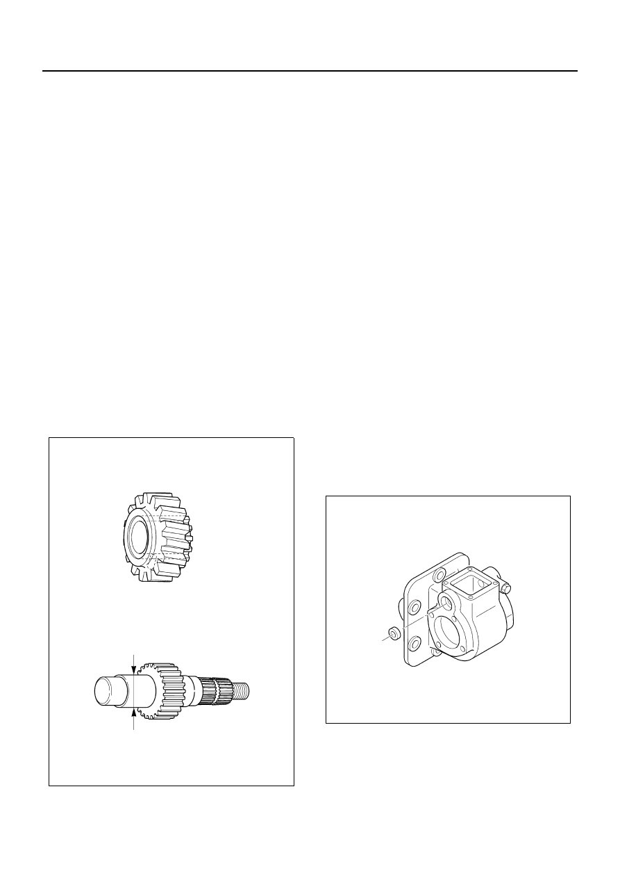
• There is extreme backlash in the output

shaft and the bearing (front and rear)
Service limit; 0.2 mm (0.008 in)

• Gears

– Check each gear. Replace it if there is extreme

fault. For minor stepped wear or rough surface,
repair it using oil stone or pencil grinder.

• Breakage, damage or wear on the cross-

section

• Wear on idle gear and shaft

Replace the idle gear (with snap ring), the
needle bearing or the taper roller bearing if
there is extreme wear.

• Gap between output shaft and output gear

(with bushing)
Service limit; 0.2 mm (0.008 in)
Replace the output gear (with bushing) if its
gap exceeds the service limit.

• Idle and output shaft

– Check for the damage or wear on the outside

surfaces of idle shaft and output shaft, wear or
damage on the spline portion, bent shaft, etc.
Replace it if the fault is extreme.

• Shift mechanism

– Check each part of shift mechanism for dam-

age, bent, stepped wear, etc. and replace it if
the fault is extreme.

• Bent or wear of shift rod
• Deformation or wear of shift arm

Thickness of shift arm
Specification; 9 mm (0.354 in)
Service limit; 8 mm (0.315 in)

• Backlash or rough movement of shift rod

and gear case

• Oil seal

– Replace the output shaft or shift rod if its con-

tact surface is damaged or deteriorated.

– Do not reuse the removed oil seal.

• Clutch

– For minor stepped wear or damage, repair it us-

ing oil stone or pencil grinder. Replace it if there
is extreme fault.

• For assembly direction of parts, refer to cross-sec-

tion diagram.

Assembly

1. Gear Case
2. Oil Seal

• Apply liquid gasket (THREE BOND 1141E) to

the circumference of oil seal and grease (BES-
CO L2 or equivalent) to the lip, and punch it into
gear case slot portion (front side).

Special tool
Oil seal installer; 5-8840-2065-0

3. Shift Rod, Shift Fork, Spring, Washer

• Put the spring and the shift fork into gear case

and pass the shift rod through them.

NPA0157E

NPA0158E

00-68 POWER TAKE OFF

4. Spring Pin

• Punch the spring pin so that the pin is flush with

the shift fork.

5. Output Shaft, Rear Bearing

• Press-fit the rear bearing into output shaft.

Special tool
Bearing installer; 5-8840-2066-0

6. Output Gear (with Bushing), Sleeve

• Insert the shift fork into the sleeve groove in the

gear case and assemble the output shaft (with
rear bearing) to the sleeve and output gear.

7. Thrust Collar, Front Bearing

• Install the thrust collar to the front side of output

shaft and press-fit the front bearing.

Special tool
Bearing installer; 5-8840-2066-0

NPA0159E

NPA0160E

NPA0161E

NPA0162E

POWER TAKE OFF 00-69

8. Adapter, Solenoid

• Apply liquid gasket (THREE BOND TB1215) to

the mounting surfaces of adapter and solenoid.
Let the cores of solenoid in-low portion and
case slot portion of adapter come out. Assem-
ble the bolt. Apply LOCTITE 242 to the bolt.

Caution:

Be careful not to damage the oil seal when the cores
come out.

Tighten:

Bolt to 25 N

⋅m (2.5 kg⋅m / 18 lb⋅ft)

Special tool
Setting tool; 5-8840-2452-1

9. Rear Cover, Oil Seal

• Fill with grease (BESCO L2 or equivalent) of

approx. 3 g to the lip of oil seal and apply liquid
gasket (THREE BOND 1141E) to the circum-
ference and assemble it to the rear cover.

Special tool

Oil seal installer; 5-8840-2064-0

• Apply liquid gasket (THREE BOND TB1215) to

the mounting surface of rear cover and LOC-
TITE 242 to the bolt threads, and assemble it.

Tighten:

Bolt to 25 N

⋅m (2.5 kg⋅m / 18 lb⋅ft)

10. Flange, Washer, Nut

• Assemble the flange to output shaft.
• Install the plain washer and spring washer, and

temporarily tighten the nut. After installing the
PTO to the transmission, tighten it to the spec-
ified torque.

Tighten:

Nut to 105 N

⋅m (10.7 kg⋅m / 77 lb⋅ft)

NPA0163E

NPA0164E

NPA0165E

NPA0166E

00-70 POWER TAKE OFF

11. Idle Gear, Taper Roller Bearing, Shim, Shaft

• To replace the taper roller bearing, punch out

the taper roller bearing outer races (two) from
the both sides of idle gear.

Special tool
Bearing installer; 5-8522-0035-0
Grip; 5-8840-0007-0

• Install the idle gear taper roller bearings (two)

and shim.

• Select the shim so that the gap shown in the il-

lustration is specification, insert the shim be-
tween the back side taper roller bearing and the
gear case, and install the idle shaft.

Gap specification between shim and case = Less than
0.08 mm (0.003 in)

12. Spring Pin

• Punch the spring pin so that it is flush with the

gear case.

13. Upper Cover

• Apply THREE BOND TB1215 to the mounting

surface and LOCTITE 242 to the bolt threads,
and assemble it to the case.

Tighten:

Bolt to 25 N

⋅m (2.5 kg⋅m / 18 lb⋅ft)

NPA0167E

NPA0168E

Shim thickness to be 
selected

mm (in)

1.50 (0.059)

1.70 (0.067)

1.60 (0.063)

1.80 (0.071)

1.65 (0.065)

1.85 (0.073)

NPA0169E

NPA0170E


Content   ..  16  17  18  19   ..