Isuzu N-Series. Manual - part 16


  Index      Isuzu     Isuzu N-Series - service repair manual


Search            


Content   ..  14  15  16  17   ..


Isuzu N-Series. Manual - part 16


POWER TAKE OFF 00-59

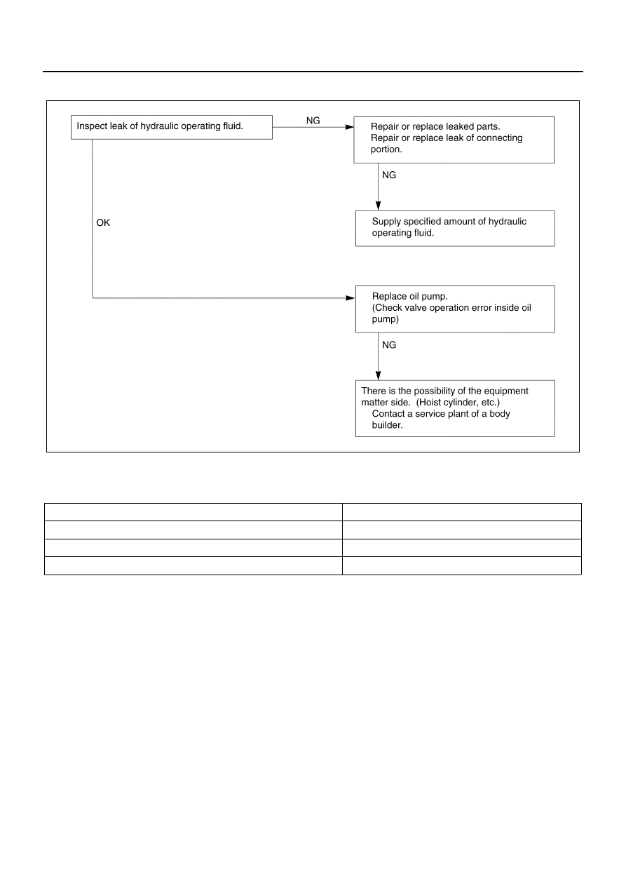
Defect 6. When a Load is Applied, The Dump Body Drops.

Main Data and Specifications

PTO with Oil Pump Assembly

Item

Specifications

Allowable maximum output torque 

N

⋅m/rpm (kg⋅m/rpm)

98/1000 (10/1000)

Deceleration ratio (speed ratio for engine)

0.678

Direction of rotation (viewed from the rear of the PTO)

Clockwise rotation

NPA0181E

00-60 POWER TAKE OFF

Fixing Torque

Special Tools

NPA0136E

Illustration

Tool Number / 

Description / Remarks

9-8529-2201-0 / Spring 

pin bar

5-8840-2432-0 / Bearing 

installer

NPA0137E

NPA0138E

5-8840-2433-0 / Oil seal 

installer

5-8840-2564-0 / Oil seal 

guide

Illustration

Tool Number / 

Description / Remarks

NPA0139E

NPA0140E

POWER TAKE OFF 00-61

5-8840-2439-0 / Joint 

(low-pressure side) PF3/

4 male screw/PF1/2 nut

5-8840-2435-0 / Test 

hose (2 m long) 

(Between oil pump and 

oil container)

Metal cap PF1/2 male 

screw 

×2)

Illustration

Tool Number / 

Description / Remarks

NPA0141E

NPA0142E

00-62 POWER TAKE OFF

ELECTRONIC CONTROL TYPE PTO ASSEMBLY

Removal and Installation

Removal

1. PTO Output Propeller Shaft

• Remove the propeller shaft, which is connected

to equipment, at the flange portion of PTO.

• Turn the PTO switch to ON, engage the gears,

and loosen the nut which tightens the PTO out-
put flange so that it can be rotated by hand at
disassembly.

2. Battery Terminal

• Disconnect the negative (

−) terminal of battery

terminal.

3. Transmission Oil

• Remove the drain plug of the transmission to

drain oil.

4. Wiring Connector

• Disconnect the two wiring connectors.

5. PTO

• Remove the bolts and nuts at six locations,

which install the PTO to the transmission, and
remove the PTO.

Installation

1. PTO

• Apply liquid gasket (THREE BOND TB1215 or

equivalent) to the mating surface of the trans-
mission case and PTO.

• Install the PTO assembly to the transmission

and tighten the bolts and nuts to the specified
torque. (Apply LOCTITE 242 to the bolt
threads.)

Tighten:

Bolt and nut to 37 N

⋅m (3.8 kg⋅m / 27 lb⋅ft)

2. Wiring Connector

• Connect wiring connector and secure them at

the bracket portion.

3. Transmission Oil

• Pour oil to the transmission.

Specified oil: BESCO gear oil transaxle (5W-
30)

Legend

1. Wiring connector

3. PTO

2. PTO output propeller shaft

4. Transmission oil

NPA0143E


Content   ..  14  15  16  17   ..