Isuzu N-Series. Manual - part 8


  Index      Isuzu     Isuzu N-Series - service repair manual


Search            


Content   ..  6  7  8  9   ..


Isuzu N-Series. Manual - part 8


POWER TAKE OFF 00-27

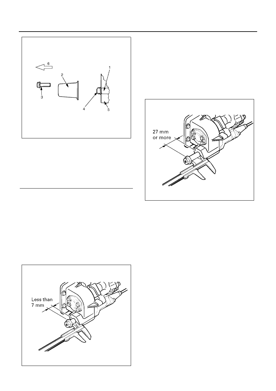
Measurement of the Amount of Spool Extrusion
(PTO Tip Portion)

1. Remove the shift cap tightening bolt of the PTO tip

portion and remove the shift cap.

2. Operate the dump lever twice or three times and

slowly set it to the “Up” position as much as possi-
ble, then firmly lock the dump lever.

3. Measure the amount of spool extrusion at “Up”

time at the PTO tip portion and check that it is a ba-
sic value.

Amount of spool extrusion: less than 7 mm (0.276 in)

4. Operate the dump lever twice or three times and

slowly set it to the “Down” position as much as pos-
sible, then firmly lock the dump lever.

5. Measure the amount of spool extrusion at “Down”

time at the PTO tip portion and check that it is a ba-
sic value.

Amount of spool extrusion: 27 mm (1.063 in) or more

Notice:

Be sure check that both amounts of spool extrusion at
“Up” and “Down” times are within basic values.

6. As a result of measurement, if the amount of spool

extrusion is within a basic value, install the shift cap
and tighten the bolt at a specified torque.

• Install the shift cap so that the groove on the lo-

cating plane can locate downward.

Tighten:

Shift cap bolt to 24 N

⋅m (2.4 kg⋅m / 17 lb⋅ft)

Notice:

If the groove is not installed facing downward, the water
intruded in the shift cap is not ejected but collected.
Rusting and freezing will cause an incorrect actuation.

Legend

1. Inner rod
2. Shift cap
3. Bolt
4. Spool extrusion portion
5. PTO tip portion
6. Truck front

NPA0056E

NPA0057E

NPA0058E

00-28 POWER TAKE OFF

Adjustment of the Amount of Spool Extrusion
(Control Cable Adjustment)

Notice:

As a result of the “Measurement of The Amount of Spool
Extrusion” described previously, if a specified extrusion
dimension cannot be obtained, adjust the control cables
on the dump lever side inside the cab and the dump le-
ver side according to the following procedure.

Control Cable Adjustment (Dump Lever Side Inside
Cab)

1. Operate the dump lever twice or three times with

the engine in the stopped state and slowly set it to
the “Up” position, then firmly lock the dump lever.

2. Measure the length “L1” on the control cable tip

and double nut side shown in the drawing and
check that it is within the following basic value.

Length “L1”: 14

±1 mm (0.55±0.039 in)

3. As a result of measurement, if the length “L1” does

not satisfy a basic value, loosen the lock nut and
adjust the control cable so that the length “L1” will
be set to a specified length “L1”, then tighten the
lock nut at a specified torque.

Tighten:

Lock nut to 6 N

⋅m (0.6 kg⋅m / 52 lb⋅in)

Control Cable Adjustment (Oil Pump Side)

1. Tighten the special nut in the cable holder loosen-

ing the lock nut, moving it to the truck rear, and
lightly pushing the control cable against the PTO
side.

2. Measure the length “L2” between the outer screw

tip portion and special nut end of the control cable
shown in the drawing and check that it is within a
basic value.

Length “L2” (Reference): 24

+1

0

 mm (0.945

+0.039

0

 in)

• As a result of check, if the length “L2” is satis-

fied, tighten the lock nut at a specified torque.

Legend

1. Bolt
2. Shift cap
3. Make groove face downward
4. Truck front

NPA0059E

NPA0060E

Legend

1. Control cable
2. Boss portion
3. Lock nut

Legend

1. Lock nut
2. Double nut
3. Control cable

NPA0061E

POWER TAKE OFF 00-29

Tighten:

Lock nut to 20 N

⋅m (2.0 kg⋅m / 14 lb⋅ft)

3. As a result of measurement, if the length “L2” does

not satisfy a basic value, adjust the control cable
according to the following procedure.

1) Loosen the special nut and move it toward the

truck rear, then set the control cable free.

2) Manually holding the control cable, take in and

out the cable to the front and rear. Obtain the
length “L3” and temporarily tighten the special
nut securing the control cable manually.

“L3” = “L2” basic value + Special Nut Thickness (10
mm)

3) Measure the length “L2” in the state of (2). If the

dimension does not satisfy a basic value, re-
peat Items (2) and (3) and adjust so that the
“L2” will be set to the basic value.

4) After having the length “L2”, tighten the special

nut at a specified torque.

Tighten:

Special nut to 142 N

⋅m (14.5 kg⋅m / 105 lb⋅ft)

Legend

1. Control cable
2. Cable holder
3. Oil pump portion
4. Special nut
5. Outer threaded portion
6. Lock nut
7. Truck front

NPA0062E

NPA0063E

Legend

1. Control cable
2. Cable holder
3. Oil pump portion
4. Special nut
5. Lock nut
6. Truck rear

Legend

1. Control cable
2. Cable holder
3. Oil pump portion
4. Special nut
5. Lock nut
6. Truck rear

NPA0064E

00-30 POWER TAKE OFF

5) After having tightened the special nut, tighten

the lock nut at a specified torque.

Tighten:

Lock nut to 20 N

⋅m (2.0 kg⋅m / 14 lb⋅ft)

4. After having adjusted the control cable, slowly op-

erate the dump lever twice or three times and re-
check the spool extrusion dimension.
(Refer to the item of Measurement of The Amount
of Spool Extrusion.)

5. After having completed all measurement and ad-

justments, set the dump lever to the “Down” posi-
tion and start the engine.

Operability of the Dump Lever, Rise of the Body
(Cargo Deck), and Inspection and Adjustment
of the Rise and Fall Reference Times

1. Check that the engine revolution per minute is

1,250 rpm and the rise and fall operations of the
body (cargo deck) are performed within the follow-
ing reference times.
Rise time = within 20 seconds
Fall time = within 20 seconds

2. Inspection of the dump lever control force and

moderation

• Inspect that the operation of the dump lever can

lightly and smoothly be performed.

Basic value = less than 10 kgf (98 N) on the dump
lever knob

• When the dump lever is in the “Up” and “Down”

positions, inspect that the lock operation can be
performed without a feeling of physical disor-
der.

3. After having repeated the “Up” and “Down” posi-

tions of the dump lever and slowly set them to the
“Down” position as much as possible, inspect the
shaft (driving shaft) between the PTO and oil
pump.

• Inspect that the shaft (driving shaft) rotates for-

ward or backward.
If the shaft slowly rotates backward, it is nor-
mal.

Legend

1. Control cable
2. Cable holder
3. Oil pump portion
4. Bolt
5. Special nut
6. Outer threaded portion
7. Lock nut
8. Truck rear

Legend

1. Special nut
2. Oil pump portion
3. Lock nut

NPA0065E

NPA0066E

NPA0067E


Content   ..  6  7  8  9   ..