Isuzu N-Series. Manual - part 5


  Index      Isuzu     Isuzu N-Series - service repair manual


Search            


Content   ..  3  4  5  6   ..


Isuzu N-Series. Manual - part 5


POWER TAKE OFF 00-15
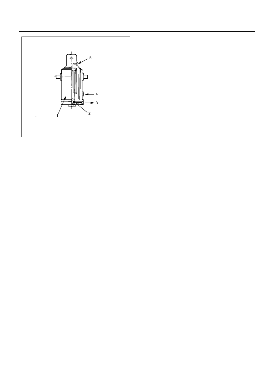
Legend

1. Cylinder main unit
2. Bypass valve
3. To oil tank
4. From oil pump (high pressure)
5. Air bleeding plug

NPA0028E

00-16 POWER TAKE OFF

CONTROL CABLE (FOR REAR DUMP TRUCK)

Removal and Installation

Removal Steps

Notice:

Because a three-rotation dump truck differs in the wiring
of a control cable from a rear dump truck, refer to the
notes on the replacement and adjustment of the control
cable for the three-rotation dump truck.

1. Lock Nut (Dump Lever Side)

• Set the dump lever to the “Down” position and

firmly lock the lever.

• Loosen the lock nut of the control cable and re-

move the cable tip from the boss portion of the
dump lever.

2. Clip (Inside Cab)

• Remove the clip from the instrument panel bot-

tom inside the cab.

Legend

1. Lock nut (dump lever side)

7. Cable stopper clip

2. Clip (inside cap)

8. Lock button

3. Lock nut (PTO side)

9. Dump lever

4. Special nut

10. PTO

5. Cable holder

11. Shift cap

6. Control cable

12. Oil pump

NPA0029E

POWER TAKE OFF 00-17

3. Lock Nut (PTO Side)

• Loosen the lock nut and move it toward the

truck front.

4. Special Nut

• Loosen the special nut and move it toward the

truck front.

5. Cable Holder

• Remove the bolt and remove the cable holder

from the PTO.

• Move the cable holder to the truck front and

provide clearance between the cable holder
and PTO.

Legend

1. Clip
2. Control cable
3. Boss portion
4. Lock nut

Legend

1. Control cable
2. Truck front
3. Lock nut
4. Special nut
5. PTO
6. Cable holder

NPA0030E

NPA0031E

Legend

1. Lock nut
2. Special nut

Legend

1. Rod end ball portion
2. Truck front
3. Cable holder
4. Bolt
5. Shift rod
6. PTO

NPA0032E

NPA0033E

00-18 POWER TAKE OFF

6. Control Cable

• Because the tip portion (PTO side) of the con-

trol cable is of a rod end ball type as shown in
the drawing, remove the cable end portion from
the cable connector groove on the PTO side
sliding it along the groove.

• Remove the cable holder from the control ca-

ble.

• Remove the control cable assembly from the

truck.

Installation Steps

1. Control Cable

• Set the dump lever to the “Down” position and

lock it.

• Install the control cable assembly in the truck.
• Move the lock nut (PTO side) and special nut of

the cable top the truck front side.

2. Cable Holder

• Assemble the cable holder in the control cable.

Legend

1. PTO
2. Rod end ball portion
3. Cable holder
4. Cable connector groove

NPA0034E

NPA0035E

Legend

1. Rod end ball portion
2. Control cable
3. Lock nut
4. Special nut
5. Cable holder

Legend

1. Special nut
2. Control cable
3. Truck front
4. Lock nut

NPA0036E


Content   ..  3  4  5  6   ..