Isuzu N-Series. Manual - part 4


  Index      Isuzu     Isuzu N-Series - service repair manual


Search            


Content   ..  1  2  3  4  5  ..


Isuzu N-Series. Manual - part 4


POWER TAKE OFF 00-11

Preparation

1. Because removal of a spare tire makes work easier

according to a truck, previously check the truck.

2. Remove the intermediate fixed clip on the truck

side between the oil pump and the oil tank of the
low-pressure side hose and set the low-pressure
hose free.

3. Prepare a cleaned hydraulic operating fluid con-

tainer (a 20 L can will do), a funnel, hydraulic oper-
ating fluid, a test hose for a special tool, and a test
hose joint.

4. Prepare the hydraulic operating fluid of about 10 L

in the cleaned hydraulic operating fluid container.

Hydraulic Operating Fluid (Turbine Oil)

Notice:

Carefully control the prepared hydraulic operating fluid
so that dust or foreign matter will not be mixed in it. Be-
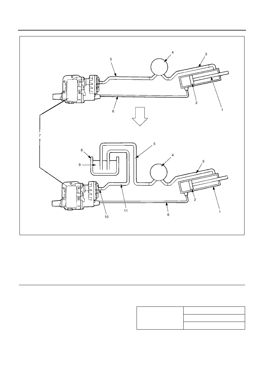
Legend

1. Hoist cylinder

7. PTO with oil pump

2. Piston

8. Hydraulic operating fluid container

3. Pipe

9. Hydraulic operating fluid

4. Oil tank

10. Test hose joint

5. Low-pressure hose

11. Test hose

6. High-pressure hose

NPA0023E

Manufactured by 
ShinMaywa Indus-
tries Co., Ltd.

0 to 30

°C (86°F): VG32

20

°C (68°F) or more: VG56

less than 10

°C (50°F): VG22

00-12 POWER TAKE OFF

sides, if the dust or foreign matter is mixed in the hydrau-
lic operating fluid, carefully handle it because it becomes
the first cause of a dump mechanism fault.

Work Procedure

1. With reference to the piping rough sketch on the

preceding page, remove the low-pressure side
hose of the oil pump and insert the port for removal
in the prepared hydraulic operating fluid container.

Notice:

Be sure to install the hydraulic oil fluid container at a
higher position than the tank pump. If it is installed at a
lower position, the oil pump may be damaged because
the hydraulic operating fluid applied in Item (4) flows in
the hydraulic operating fluid container and air is mixed in
the hose.

Notice:

When inserting the removed low-pressure hose in the
hydraulic operating fluid, remove the hose band, be sure
to clean the hose port, and handle the hose so that dust
or foreign matter will not be mixed in the hydraulic oper-
ating fluid.

2. Remove the low-pressure side hose joint of the oil

pump.

3. Install the test hose and connecting joint on the

low-pressure side of the oil pump.
Joint (low-pressure side): 5-8840-2439-0
Test hose: 5-8840-2435-0

4. Use the funnel from the fluid container insertion

side of the test hose to fill the hose with the hydrau-
lic operating fluid and insert the hose port in the hy-
draulic operating fluid container.

Notice:

The test hose is filled with hydraulic operating fluid to
minimize the mixture of air in the hydraulic circuit.
Further, fix the two hoses inserted in the fluid container
not to jump out from the hydraulic operating fluid.

5. Start the engine and depress the clutch pedal in

the idling state, then set the dump lever to the “Up”
position.

6. When slowly releasing the clutch pedal and oper-

ating the oil pump, the body (cargo deck) starts be-
ing raised.

Notice:

At this time, check that the air mixed in the hydraulic cir-
cuit is discharged in the hydraulic operating fluid as blow
holes.

Legend

1. Hoist cylinder
2. Oil tank
3. Low-pressure hose
4. Hydraulic operating fluid container
5. Hydraulic operating fluid
6. PTO with oil pump
7. High-pressure hose

NPA0024E

Legend

1. High-pressure hose
2. Test hose
3. Funnel
4. Low-pressure hose
5. Insert
6. To oil tank
7. Hydraulic operating fluid container
8. Hydraulic operating oil pump
9. PTO with oil pump

NPA0025E

POWER TAKE OFF 00-13

7. Raise the body (cargo deck) up to the most raised

position in the idling state and apply the safety rod
and the safety strut to the body (cargo deck). Then
prevent drop and check safety.

8. After having the body (cargo deck), stop the engine

and remove the test hose installed in Item (3) from
the oil pump, then release it from the fluid contain-
er.

9. Remove the test hose connecting joint from the

low-pressure side of the oil pump and install the
joint for connecting the original low-pressure hose.

10. Release the low-pressure side hose removed from

the oil pump and soaked in the fluid container in
Item (1) and install it on the low-pressure side of
the oil pump as before, then firmly tighten the hose
band.

Notice:

For the subsequent work procedure, supply hydraulic
operating fluid or perform the air bleeding of hydraulic
operating fluid in accordance with each item of the text
in the “Supply Procedure of Hydraulic Operating Fluid”
or the “Air Bleeding Procedure of Hydraulic Operating
Fluid”.
Be careful of excessive supply of hydraulic operating flu-
id.
If an excessive amount of hydraulic operating fluid ex-
ceeding the specified amount is supplied when supply-
ing the hydraulic operating fluid at the rise of the body
(cargo deck), the hydraulic circuit will be filled with the
hydraulic operating fluid because the volume of the fluid
in the oil tank is increased more than necessary at the
drop of the body (cargo deck).
According, the body (cargo deck) will not be dropped
from a predetermined place. If it is dropped forcibly, ex-
cessive pressure applies to the hydraulic circuit (con-
sisting of the hose, pipe, and tank) resulting in its
damage or a leak of oil.

Total Replacement of Hydraulic Operating
Fluid

Request a service network (SS store) of a body manu-
facturer of the total replacement of hydraulic operating
fluid.

Air Bleeding Procedure of Hydraulic Oper-
ating Fluid

Notice:

Be sure to supply a specified amount of hydraulic oper-
ating fluid using a cleaned oil supply container paying
full attention so that dust or foreign matter will not be
mixed in. After having supplied oil, firmly tighten each
plug.

[Rear Dump Truck]

<Manufactured by Shin Maywa Industries, Co., Ltd.>
Hydraulic Operating Fluid Supply

1. Raise the body (cargo deck) in accordance with the

“How to raise the body (cargo deck)” described
previously.

2. Remove oil filler plug (1) and level plug (2) of the oil

tank and supply oil from the oil filler port until the
hydraulic operating fluid flows out from level plug
(1), then tighten plug (2).

3. Remove oil filler port plug (5) from the cylinder

head, supply the hydraulic operating fluid to
“Chamber A” so that no air will be left to fill the
chamber with the fluid, and tighten oil filler port plug
(5).

Air Bleeding Method

1. Raise the body (cargo deck) in accordance with the

“How to raise the body (cargo deck)” described
previously.

2. At the maximum rise, cylinder shaded portions

“Chamber A” and “Chamber B” shown in the draw-
ing are fully filled with hydraulic operating fluid and
Section “C” is filled with the hydraulic operating flu-
id up to its level position.

Notice:

Supplying hydraulic operating fluid more than necessary
will cause a fault.

Legend

1. Oil filler port
2. Level plug
3. Oil pump
4. Hoist cylinder
5. Oil filler port
6. Piston rod
7. Oil tank

NPA0026E

00-14 POWER TAKE OFF

3. First remove the oil tank oil filler port plug of (1).

Then start the engine, operate the dump lever, and
drop and raise the body (cargo deck) several
times. Consequently, air is naturally released usu-
ally.

4. Tighten the oil tank oil filler port plug of (1).

Notice:

If the work of Item (2) is performed with plug (1) tight-
ened, air may not be released.

Notice:

When air is mixed in hydraulic operating fluid and be-
comes whitely foamy, the air will not be released.
So raise the body (cargo deck) and remove plugs (1)
and (5). When the hydraulic operating fluid is left alone
about for 30 to 60 minutes, the air is naturally separated.
Re-supply oil in accordance with the procedure of Items
(2) and (3) of the “Supply Procedure of Hydraulic Oper-
ating Fluid”.
Principles Under Which Air Is Released
Between “B” and “C”
For Chamber “B” filled with hydraulic operating fluid,
when the body (cargo deck) is dropped, the piston rod is
dropped and the hydraulic operating fluid in “Chamber
B” passes through the oil pump and is returned to the oil
tank. At this time, if air is mixed in, it is discharged from
“Surface C” in the oil tank as blow holes.
Between “A” and “C”
The hydraulic operating fluid pressurized and sent via
the oil pump is sent from “Chamber C” to “Chamber B”.
The piston cylinder is raised and the hydraulic operating
oil in “Chamber A” is sent to “Chamber C”, and then the
air is discharged for the same reason as between “B”
and “C”.

[Three-Rotation Dump Truck]

<Manufactured by Shin Maywa Industries, Co., Ltd.]
Hydraulic Operating Fluid Supply

1. Raise the body (cargo deck) in accordance with the

“How to raise the body (cargo deck)” described
previously.

2. Remove oil filler plug (1) and level plug (2) of the oil

tank and supply oil from the oil filler port until the
hydraulic operating fluid flows out from level plug
(2), then tighten plug (2).

Notice:

Supplying hydraulic operating fluid more than necessary
will cause a fault.

3. Set the dump lever to the “Up” position with the en-

gine in the idling state.

4. When loosening the air bleeding plug (3) of the cyl-

inder about once or twice, air is discharged and
then hydraulic operating fluid is ejected. So quickly
tighten the plug.

Notice:

When air is mixed in hydraulic operating fluid and be-
comes whitely foamy, the air is not released. So raise
the body (cargo deck) and leave the hydraulic operating
fluid alone about for one hour. The air in the hydraulic
operating fluid is naturally separated and subsequently
air can be released.
Even when performing air bleeding work, raise the body
(cargo deck) in accordance with the “How to Raise The
Body (cargo deck)” described previously.

Legend

1. Oil filler port
2. Level plug
3. Oil tank

NPA0027E


Content   ..  1  2  3  4  5  ..