Isuzu Rodeo UE. Manual - part 628
SUN ROOF/CONVERTIBLE TOP
8I–9
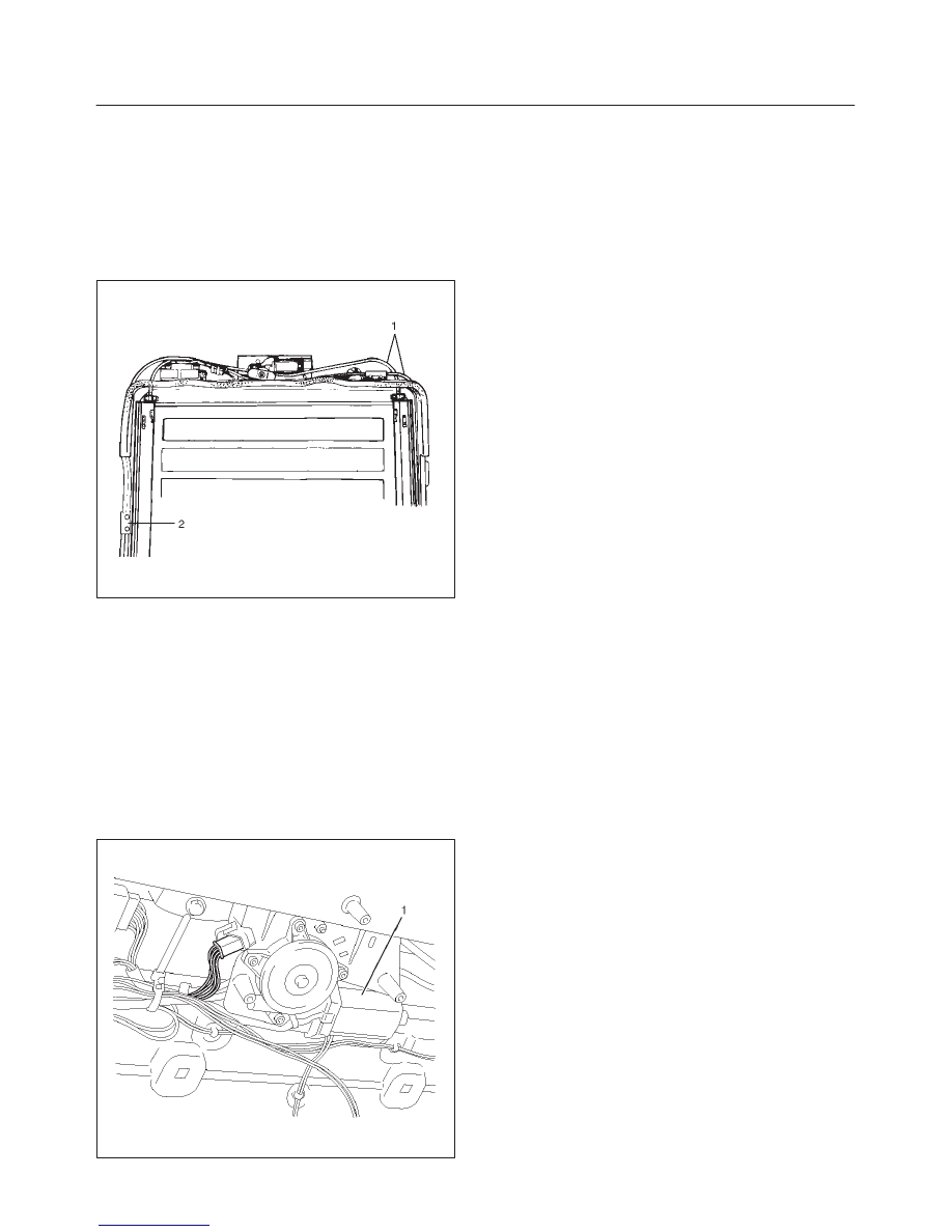
Limit Switch
Removal
1. Disconnect the battery ground cable.
2. Remove the sun roof drive unit assembly (1) to
remove the limit switch (2).
Refer to the Sun Roof Frame Complete Assembly
disassembly steps in this section.
665RS025
Installation
To install, follow the removal steps in the reverse order.
Sun Roof Motor
Removal
1. Disconnect the battery ground cable.
2. Remove the headlining (2).
Refer to the Headlining removal steps in
Exterior/Interior Trim section.
3. Remove the sun roof motor (1).
f
Disconnect the connector.
f
Remove three nuts and two screws.
665RW014
Installation
To install, follow the removal steps in the reverse order.