Isuzu Rodeo UE. Manual - part 83


  Index      Isuzu     Isuzu Rodeo UE - service repair manual 1999 year


Search            


Content   ..  81  82  83  84   ..


Isuzu Rodeo UE. Manual - part 83


4C–41

DRIVE SHAFT SYSTEM

Universal Joint Disassembly
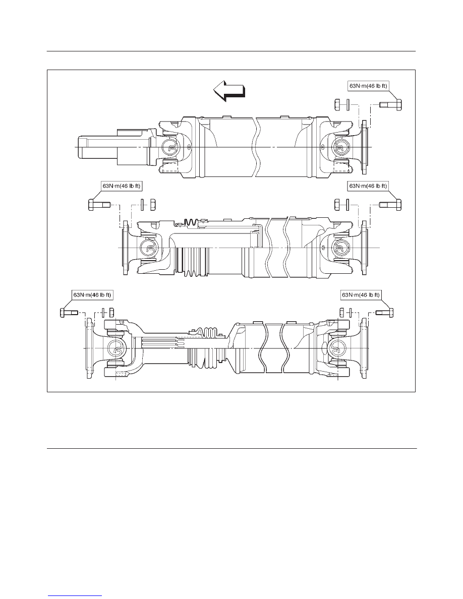
401RX005

Legend

(1) Spline Yoke
(2) Spider
(3) Propeller Shaft Assembly
(4) Spider

(5) Flange Yoke
(6) Bearing
(7) Snap Ring
(8) Flange Yoke

NOTE: Aluminum is softer than steel.  Care must be
taken not to remove excessive material or damage
bearing holes.
If the vehicle has aluminum tube type propeller shaft,
flange yoke, boot kit, journal kit can be replaced. If other
parts are damaged, replace propeller shaft as assembly.

4C–42

DRIVE SHAFT SYSTEM

1. Apply alignment marks on the yokes of the universal

joint, then remove the snap ring.

401RW024

If the snap ring is stuck in position, remove paint from
the hole in the yoke or tap around the edge of the
bearing lightly with a soft drift.

401RW025

2. Set the yoke in the arbor press with a piece of tube

stock beneath it.
Place a solid plug on the upper bearing and press it
through to release the lower bearing.

401RW027

3. If the bearing will not pull out by hand after pressing,

tap the base of the lug near the bearing to dislodge it.

4. To remove the opposite bearing, turn the yoke over

and straighten the spider in the open spider hole.
Then carefully press on the end of the spider so the
remaining bearing moves straight out of the bearing
spider hole.  If the spider or bearing are cocked, the
bearing will score the walls of the spider hole and ruin
it.

401RW026

4C–43

DRIVE SHAFT SYSTEM

5. Repeat this procedure on the remaining bearing to

remove the spider from the yoke. 

Inspection

f

Propeller shaft for run-out Aluminum tube type.

Static run-out limit : 1.0 mm(0.04 in)

TIR full length of tubing maximum.

(TIR : Total Indicator Reading)

f

Propeller shaft for runout (Steel tube type).

Static runout limit : 0.13 mm(0.005 in)

TIR on the neck of the slip tube shaft (with a
boot).

0.25 mm(0.010 in)

TIR on the ends of the tubing 3 inch from the
welds.

0.38 mm(0.015 in)

TIR at the linear center of the tube.

0.38 mm(0.015 in)

TIR for the full length of tube with 30” or less of
tubing.

(TIR: Total Indicator Reading)

401RW017

f

Play in universal joint.

Limit: Less than 0.15 mm(0.006 in)

f

Spider pin should be smooth and free from fretting or
galling.
Visible signs of needle presence is normal, but wear
should not be felt.

401RW028

f

Preload of the universal joint.
Preload should be 0 to 49 N (0 to 11.0 lb).
Joints should rotate smoothly and freely and should
exhibit no rough or ratchety movement.

401RW019

f

Inspect splines of slip joint for wear.
The nylon-coated spline should be free from nicks
and dings and the underlying steel spline should not
be visible.
After cleaning the nylon coating spline, the coating
should exhibit only slight indicator of wear.
Grease volume is approximately 10 grams of grease
in total.  Grease should be evenly applied to both the
female and  the male slip splines using a small brush.
After assembly of the slip joint, the sliding joint should
be fully worked from the full collapsed to the full
extended position.

4C–44

DRIVE SHAFT SYSTEM

f

Aluminum tube type only: Inspect the aluminum
tubing for surface scratches and dents.  These
scratches may not exceed 0.2 mm (0.008 in) in depth.

401RW022

f

Aluminum tube type only: Visually inspect the circle
welds and fittings for any signs of cracks or signs of
deterioration.  If there are any cracks that exceed 0.2
mm (0.008 in) in depth, the assembly must be
replaced.

f

Aluminum tube type only: Check to be sure there are
no missing balance weights.  If balance weights are
missing and void has occurred in the aluminum tubing
greater than 0.2 mm (0.008 in), the assembly must be
replaced.

Universal Joint Reassembly

1. Pack the four grease cavities of the spider with a high

quality, extreme pressure N.L.G.I. Grade 2 grease.
Do not add additional grease to bearing cup
assembly.

2. Move one end of the spider to cause a trunnion to

project through the spider hole beyond the outer
machined face of the yoke lug.  Place a bearing over
the trunnion diameter and align it to the spider hole.
Using an arbor press, hold the trunnion in alignment
with the spider hole and place a solid plug on the
upper bearing.  Press the bearing into the spider hole
enough to install snap ring.

401RW026

3. Install a snap ring.

NOTE: Be sure the snap rings are properly seated in the
grooves.

4. Repeat steps 2 and 3 to install the opposite bearing.  If

the joint is stiff, strike the yoke ears with a soft
hammer to seat the bearing.

5. Align the setting marks and join the yokes.


Content   ..  81  82  83  84   ..