Isuzu Rodeo UE. Manual - part 82


  Index      Isuzu     Isuzu Rodeo UE - service repair manual 1999 year


Search            


Content   ..  80  81  82  83   ..


Isuzu Rodeo UE. Manual - part 82


4C–37

DRIVE SHAFT SYSTEM

401RW018

7. Install snap ring.
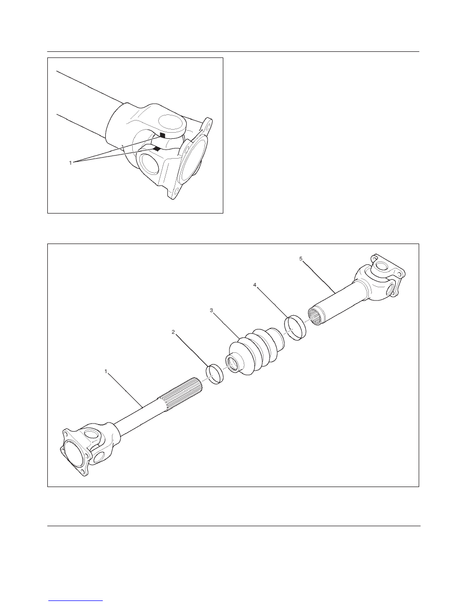
Reassembly

401RW032

Legend

(1) Sleeve Yoke
(2) Clamp

(3) Boot
(4) Clamp
(5) Tube Assembly

4C–38

DRIVE SHAFT SYSTEM

1. Apply grease evenly to both the female and male

splines.

2. Apply a small amount of grease by finger to the outer

lips of the boot.

3. Slide the boot onto the yoke shaft being careful not to

damage the spline coating or boot.

4. Insert the yoke shaft spline into the sleeve being

careful to maintain proper phasing.  The spider holes
should be in line and as per originally marked prior to
disassembly.

5. Position boot onto sleeve and yoke shaft in final

position over boot grooves.

6. Attach boot clamps and secure using pliers.
7. Be sure clamp is properly seated and secure.

Main Data and Specifications

General Specifications

Transmission

M/T

A/T

Length (between two spiders
center)

367.2 mm (14.81 in)

542.2 mm (21.35 in)

Torque Specifications

401RX001

4C–39

DRIVE SHAFT SYSTEM

Rear Propeller Shaft

Rear Propeller Shaft and Associated Parts

401RX003

Legend

(1) Bolt, Nut and Washer (Transfer Side)

(2) Rear Propeller Shaft
(3) Bolt, Nut and Washer (Rear Axle Side)

Removal

1. Raise the vehicle on a hoist.

NOTE: Apply alignment marks on the flange at the rear
propeller shaft both front and rear side.

2. Remove transfer side bolt, nut and washer (except

spline yoke type).

3. Remove rear axle side bolt, nut and washer.
4. Remove rear propeller shaft.

NOTE: Plug the hole of the transmission rear end to
prevent oil leakage (spline yoke type only).

Installation

NOTE: Never install the shaft assembly backwards.
Never insert bar between yoke lugs when tightening or re-
moving bolts.
Completely remove the dust or foreign matter from the
connecting surface of flange coupling on each end of the
propeller shaft.

1. Align the mark which is applied at removal.
2. Install rear propeller shaft and tighten the bolts to the

specified torque.

Torque: 63 N·m(46 lb ft)

4C–40

DRIVE SHAFT SYSTEM

Slip Joint Disassembly

401RX004

Legend

(1) Spline Yoke and Universal Joint Assembly
(2) Clamp

(3) Boot
(4) Clamp
(5) Tube and Universal Joint Assembly

1. Lay the shaft horizontally on a bench and secure.
2. Indicate the original assembled position by marking

the phasing of the shaft prior to disassembly.

3. Using the flat blade of a screwdriver, pry the loose end

of the boot clamp upwards and away from the
propeller shaft boot. Be careful not to damage the
boot.

4. When boot clamps becomes loose, remove by hand.
5. Repeat for the other boot clamp.
6. Remove the slip yoke assembly from the driveshaft,

by securing the boot with one hand and pulling on the
slip yoke.

7. Remove the boot from the shaft assembly.


Content   ..  80  81  82  83   ..