Isuzu Rodeo UE. Manual - part 78
4C–21
DRIVE SHAFT SYSTEM
Inspection And Repair
Inspect the removed parts. If there are abnormalities
such as wear and damage, take corrective action or
replace.
Visual Check
1. Check and see if the inner shaft has such
abnormalities as wear and damage.
412RW014
2. When inspecting the inner shaft, be sure to check and
see if its splined part is twisted, worn, or cracked. If so,
replace with a new shaft. In case such an abnormality
in its gear part (a slide with sleeve), replace the shaft.
420RS008
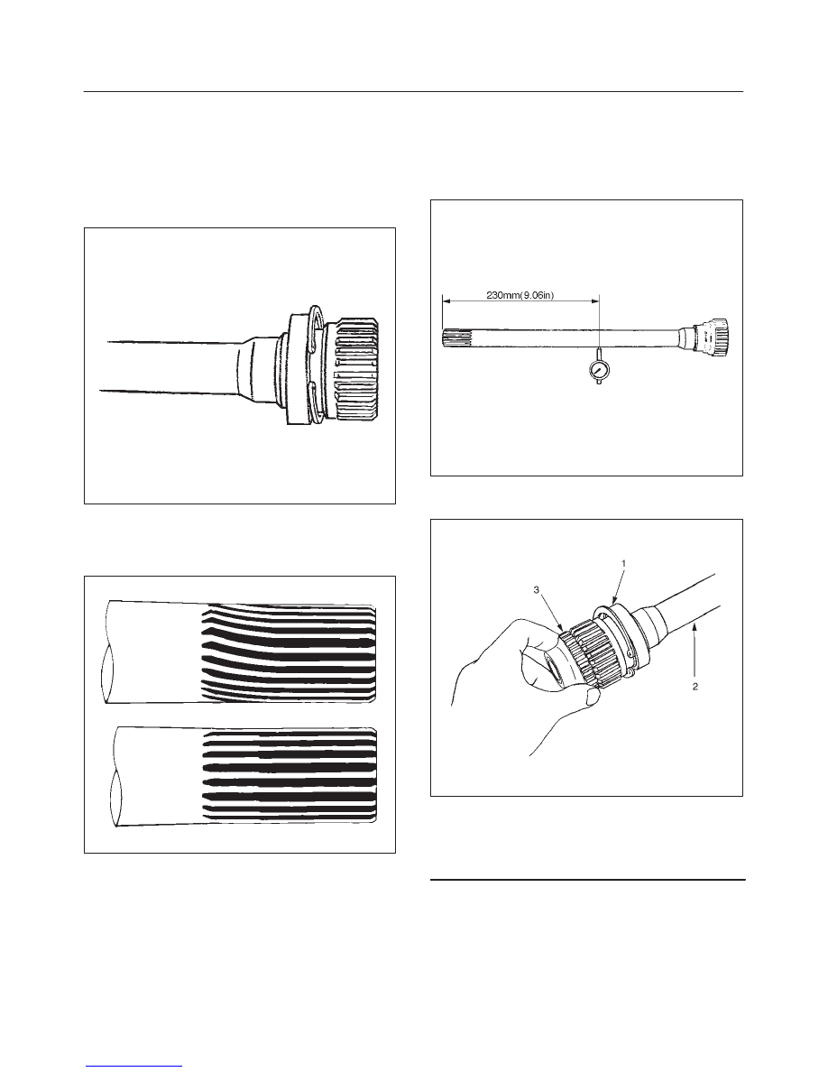
Inner Shaft Run–Out
With both end centers supported, rotate the shaft slowly
and measure deflection with a dial gauge.
Limit: 0.5 mm (0.02 in)
NOTE: Do not heat the shaft to correct its bend.
412RS026
Inner Shaft Bearing
412RW006
Legend
(1) Inner Shaft Bearing
(2) Inner Shaft
(3) Clutch Gear
1. Inspect the state of inner shaft bearing. If any
abnormality such as smoothlessness is found,
replace with a new inner shaft bearing.
2. Insert a clutch gear and check the state of needle
bearing.
3. If there is an abnormality such as smoothlessness,
replace the needle bearing.