Isuzu KB P190. Manual - part 65


  Index      Isuzu     Isuzu KB P190 - service repair manual 2007 year


Search            


Content   ..  63  64  65  66   ..


Isuzu KB P190. Manual - part 65


3A-12 FRONT ALIGNMENT 
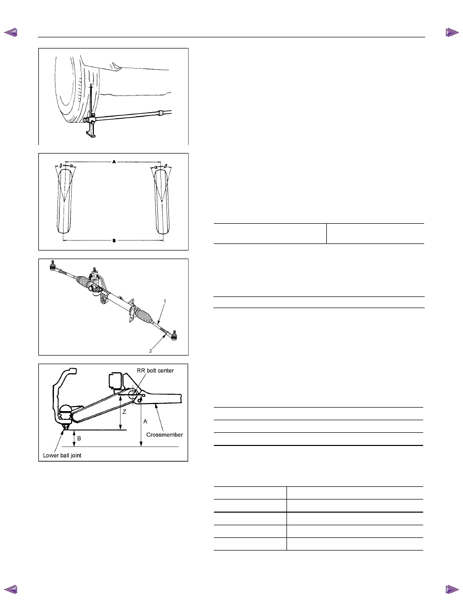


Toe-in Adjustment 

Measurement should be taken with the vehicle on a surface 
plate. 
If a surface plate is not available, toe-in should be checked 
with the vehicle parked on a level floor. 
1.  Set front wheels to straight ahead position. 

2.  Align the toe-in gauge with center height of each wheel at 

front end. 

3.  Apply center marks to each wheel, then take measurement

of distance A between the center marks on each wheel. 

4. Slowly move the vehicle rearward until the center marks 

reach the rear end position. 

5. Take measurement of distance B between the center

marks at rear end. 

The toe-in can be calculated with the following formula. 
Toe-in = B - A 
Toe-in mm 

(in)


4

×2 (High ride suspension) 

4

×4 

0

±2 (0±0.08) 


To adjust the toe-in angle, loosen the lock nuts (2) on the tie 
rod (1) and turn the tie rod. Turn both rods the same amount, 
to keep the steering wheel centered. 
Lock Nut Torque 

N

⋅m (kgf⋅m/lb⋅ft)

98

±6.0 (10.0±0.6 / 72.3±4.3) 


RTW330SH000201 


Trim Height 

Trim Height : at Curb Weight 
Trim height (Z) = A - B 
 mm 

(in)


165

±5 (6.5±0.20) (Philippine only) 

140

±5 (5.5±0.20) (Except Philippine) 


MAXIMUM STEERING ANGLE 


4

×2 (High ride suspension), 4×4 

Outside wheel 

32.8

° (Philippine only) 

Inside wheel 

35.0

° (Philippine only) 

Outside wheel 

32.1

° (Except Philippine) 

Inside wheel 

34.4

° (Except Philippine) 

FRONT ALIGNMENT  3A-13 


RTW53ASH000301 


FRT Buffer clearance (Reference Data) 

mm(in)


4

×2 (High ride suspension), 4×4 

29.7(1.17) 


Adjustment 

Adjust the trim height by means of the adjusting bolt on the 
height control arms. 
1.  Check and adjust the tire inflation pressures. 

2.  Park the vehicle on level ground and move the front of the

vehicle up and down several times to settle the suspension.


410RS001 


3.  Make necessary adjustments with the adjusting bolt on the 

height control arms. 


RTW63ASH000101 


RR Buffer clearance (Reference Data) 

mm(in)


4

×2 (High ride suspension), 4×4 

80.0 (3.15) 


POWER-ASSISTED STEERING SYSTEM 3B-1 

SECTION 3B 

POWER-ASSISTED STEERING SYSTEM 

TABLE OF CONTENTS 


PAGE 

General Description.........................................................................................................   3B –  4 

Power Steering System Test ..........................................................................................   3B –  7 

Maintenance .....................................................................................................................  3B –  8 

Fluid Level ........................................................................................................................  3B –  8 

Bleeding The Power Steering System ...........................................................................   3B –  8 

Bleeding Procedure.........................................................................................................   3B – 8 

Flushing The Power Steering System............................................................................   3B –  8 

Steering Wheel Free Play Inspection .............................................................................   3B –  9 

Front End Alignment Inspection and Adjustment.........................................................   3B –  9 

Special Tools ...................................................................................................................  3B –  10 

Power Steering Unit.........................................................................................................   3B –  11 

Power Steering Unit and Associated Parts...............................................................   3B –  11 

Removal .......................................................................................................................   3B –  11 

Installation ...................................................................................................................  3B –  12 

Power Steering Unit Disassembled View..................................................................   3B –  13 

Disassembly ................................................................................................................  3B – 14 

Inspection and Repair.................................................................................................   3B –  14 

Reassembly .................................................................................................................  3B – 14 

Main Data and Specifications ....................................................................................   3B –  15 

Special Tools ...............................................................................................................   3B –  16 

Power Steering Pump......................................................................................................   3B –  17 

Power Steering Pump and Associated Parts (4JH1-TC, 4JA1-T) ............................   3B –  17 

Removal .......................................................................................................................   3B –  17 

Installation ...................................................................................................................  3B –  17 

Power Steering Pump Disassembled View ..............................................................   3B –  18 

Disassembly ................................................................................................................  3B – 19 

Inspection and Repair.................................................................................................   3B –  19 

Reassembly .................................................................................................................  3B – 20 

Main Data and Specifications ....................................................................................   3B –  20 

3B-2 POWER-ASSISTED STEERING SYSTEM 


 PAGE 

Power Steering Pump (4JJ1-TC, 4JK1-TC)....................................................................   3B –  22 

Power Steering Pump and Associated Parts............................................................   3B –  22 

Removal .......................................................................................................................   3B –  22 

Installation ...................................................................................................................  3B –  22 

Power Steering Pump Disassembled View ..............................................................   3B –  23 

Disassembly ................................................................................................................  3B – 24 

Inspection and Repair.................................................................................................   3B –  24 

Reassembly .................................................................................................................  3B – 25 

Main Data and Specifications ....................................................................................   3B –  25 

Supplemental Restraint System Steering Wheel & Column ........................................   3B –  27 

Service Precaution......................................................................................................   3B –  27 

SRS Connectors..........................................................................................................   3B –  27 

Inflator Module .................................................................................................................  3B –  28 

Inflator Module and Associated Parts .......................................................................   3B –  28 

Removal .......................................................................................................................   3B –  29 

Inspection and Repair (with SRS air bag) .................................................................   3B –  31 

Installation ...................................................................................................................  3B –  31 

Steering Wheel.................................................................................................................  3B –  33 

Steering Wheel and Associated Parts.......................................................................   3B –  33 

Removal .......................................................................................................................   3B –  33 

Installation ...................................................................................................................  3B –  36 

The adjustment method in case a mark has not been applied ....................................   3B –  38 

Combination Switch ........................................................................................................   3B – 39 

Combination Switch and Associated Parts ..............................................................   3B –  39 

Removal .......................................................................................................................   3B –  39 

Installation ...................................................................................................................  3B –  42 

Lock Cylinder ...................................................................................................................  3B –  45 

Lock Cylinder and Associated Parts .........................................................................   3B –  45 

Removal .......................................................................................................................   3B –  45 

Installation ...................................................................................................................  3B –  48 

System Inspection (with SRS air bag).......................................................................   3B –  50 


Content   ..  63  64  65  66   ..