Isuzu KB P190. Manual - part 40


  Index      Isuzu     Isuzu KB P190 - service repair manual 2007 year


Search            


Content   ..  38  39  40  41   ..


Isuzu KB P190. Manual - part 40


2A-6  FRAME AND BUMPER 


Important Operations - Removal 

1.  Front Combi Lamp Assembly 

2. Radiator Grille 
Refer to the Radiator Grille in this section. 


RTW52ASH000101 


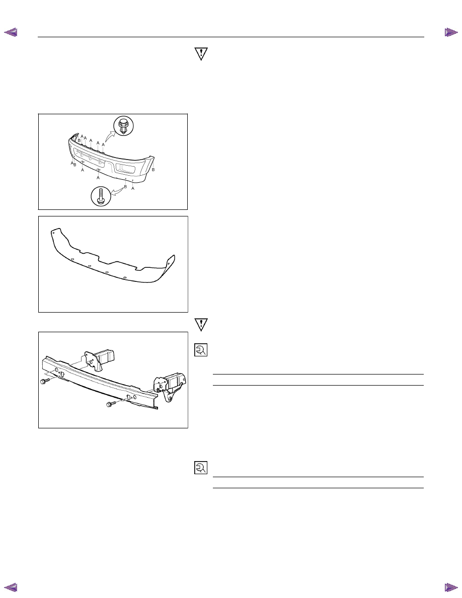
3.  Front Bumper Fascia 

•  Remove the 9 clips and 4 screws. 
•  Disconnect the fog light harness connectors. 


RTW52ASH000401 


6. Bumper Seal 
Remove 6 clips. 


Important Operations - Installation 


10. Front Bumper Impact Bar Assembly 
Tighten the fixing bolts to the specified torque. 

 
Torque N

⋅m(kgf⋅m/lb⋅ft)

62 (6.3 / 46) 


7.  Front Bumper Flare Assembly 
Tighten the fixing nuts to the specified torque. 

 
Torque N

⋅m(kgf⋅m/lb⋅in)

7 (0.7 / 61) 


FRAME AND BUMPER  2A-7 


5. Fog Light 
Tighten the fixing nuts to the specified torque. 

 
Torque N

⋅m(kgf⋅m/lb⋅in)

7 (0.7 / 61) 


2A-8  FRAME AND BUMPER 

REAR STEP BUMPER 


  REMOVAL AND INSTALLATION 


RTW72ALF000401 


Removal Steps   

  1. Rear step bumper assembly 
  2. Side step pad 


3. License plate light 

  4. Rear bumper center pad 


5. Extension harness 


6. Center bar 


7. Shell 


8. Back bar / corner brace 


9. Reinforcement assembly 


Installation Steps 

  9. Reinforcement assembly 


8. Back bar / corner brace 

  7. Shell 
  6. Center bar 


5. Extension harness 


4. Rear bumper center pad 


3. License plate light 


2. Side step pad 

  1. Rear step bumper assembly 


FRAME AND BUMPER  2A-9 


Important Operations - Removal 

1.  Rear Step Bumper Assembly 

•  Remove the 3 bolts from each side. 
•  Disconnect the extension harness connector. 


1

1


RTW72ASH000701 


2.  Side Step Pad 

•  Push out the 4 fixing portions (1) of side step pad from

the back face of the rear step bumper. 


RTW72ASH000801 


4.  Rear Bumper Center Pad 

•  Remove the 2 clips (1) from both ends of the center pad.
•  Push out the 5 fixing portions (2) of the center pad from

the back face of the rear step bumper. 


RTW72ASH000901 


Important Operations - Installation 

9. Reinforcement assembly 

•  Tighten the fixing bolts to the specified torque. 

Bolt (5) 

Torque N

⋅m(kgf⋅m/lb⋅ft)

85 (8.7 / 63) 


7. Shell 

Bolt (2), (3) 

Torque N

⋅m(kgf⋅m/lb⋅ft)

42 (4.3 / 31) 


6. Center bar 

Bolt (1) 

Torque N

⋅m(kgf⋅m/lb⋅in)

7 (0.7 / 61) 


Bolt (4) 

Torque N

⋅m(kgf⋅m/lb⋅ft)

18 (1.8 / 13) 


Content   ..  38  39  40  41   ..