Isuzu D-Max / Isuzu Rodeo (TFR/TFS). Manual - part 1855


  Index      Ford     Isuzu D-Max / Isuzu Rodeo TFR/TFS series - service repair manual 1997-2003 year


Search            


Content   ..  1853  1854  1855  1856   ..


Isuzu D-Max / Isuzu Rodeo (TFR/TFS). Manual - part 1855


7A2-36  DIAGNOSIS


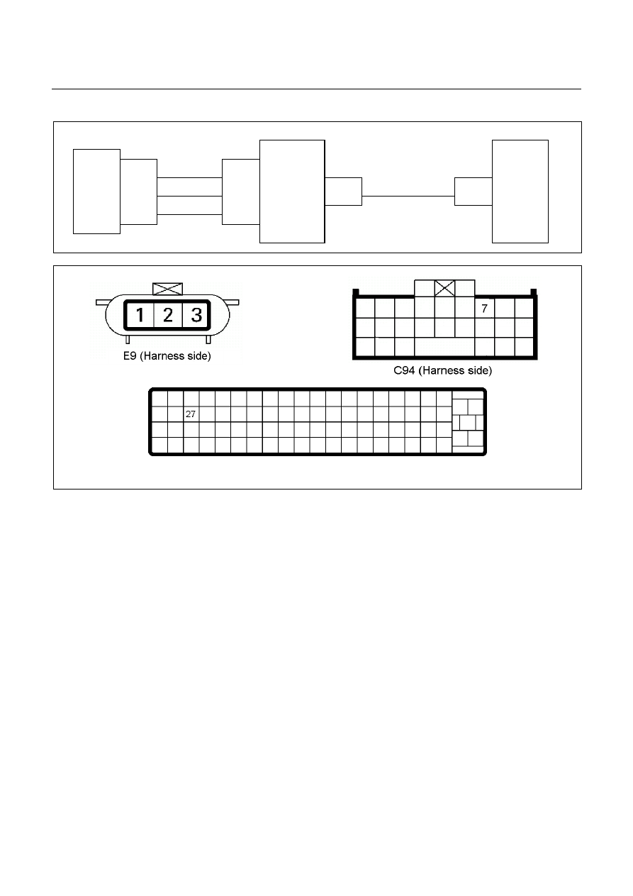
DTC P0727 (Flash Code 13) Engine Revolution Sensor No Signal


 RED 

TDC 

Sensor 

TCM 


A7 

C94 

(7) 

 BLK/RED

 WHT 

C56

(27)

E9 

(1) 


(2) 


(3)


C57 

(98) 


(90) 


(101)


ECM 


C56 (ECM-A) 

 
Setting Condition: 

•

  The engine speed becomes 0 rpm for 2 seconds while the vehicle is running at the over 40 km/h. 

 
Fail Safe: 

•

  Lock-up is inhibited. 

 
Possible Cause: 

•

  Crank position sensor malfunction. 

•

  Sensor wheel (flywheel) malfunction. 

•

  Large sensing gap between speed sensor and sensor wheel (flywheel). 

•

  Faulty input signal from crank position sensor to ECM. 

•

  Signal wire open circuit or short circuit to battery between ECM A24 and TCM terminal A7 (C94). 

•

  Poor connection of each connector. 

 
Reference: 
When the engine speed 1500rpm, following signal is outputted. 
Measurement terminal: A7 (C94) and B5 (C95) 


DIAGNOSIS  7A2-37


Engine Speed Sensor Reference Wave Form 


Measurement Terminal: A7 (+) 

B5(-) 

Measurement Scale: 5V/div 

20ms/div 

Measurement Condition: At engine speed 1500rpm


7A2-38  DIAGNOSIS


DTC P0717 (Flash Code 14) Turbine Speed Sensor No Signal


Turbine 

Sensor 

TCM 


B3 

H23

(9)

C95 

(3) 

E31 

(2) 

(1) 

(3) 

E10 

Key SW  

BRN/RED

  WHT 

  BLK 

BRN/RED


Speed Sensor 

Turbine Sensor 

 
Setting Condition: 

•

  The turbine speed below 300 rpm for 2 seconds while the vehicle is running at the speed over 40 km/h with the 

engine speed over 1500 rpm in the D, 3, 2, or L range. 

 
Fail Safe: 

•

  When the vehicle is running, the gear position selected at the trouble detection is held and the lock-up is 

inhibited. 

•

  After the vehicle stopped, all solenoid operations stop (OFF) and the gear is fixed to the 3rd. 

 
Possible Cause: 

•

  Turbine speed sensor malfunction. 

•

  Sensor wheel (reverse & high clutch drum) malfunction. 

•

  Large sensing gap between speed sensor and sensor wheel (reverse & high clutch drum). 

•

  Sensor wire open circuit, short circuit to battery or short circuit to ground between turbine speed sensor terminal 

1 and TCM terminal B3 (C95). 

DIAGNOSIS  7A2-39


•

  Sensor wire open circuit or short circuit to ground between turbine speed sensor terminal 2 and power supply 

circuit. 

•

  Sensor wire open circuit or short circuit to battery between turbine speed sensor terminal 3 and ground circuit. 

•

  Poor connection of each connector. 

 
Reference: 
When the vehicle speed 20km/h at L range in 1st gear, following signal is outputted. 
Measurement terminal: B3 (C95) and B5 (C95) 
-AC range by circuit tester: Approximately 6.2 V 


Turbine Sensor Reference Wave Form 


Measurement Terminal: B3 (+) 

B5 (-) 

Measurement Scale: 5V/div 

500ms/div 

Measurement Condition: Vehicle speed 20km/h at L range in 1st gear 


Content   ..  1853  1854  1855  1856   ..