Infiniti I30 (A33). Manual - part 380
4
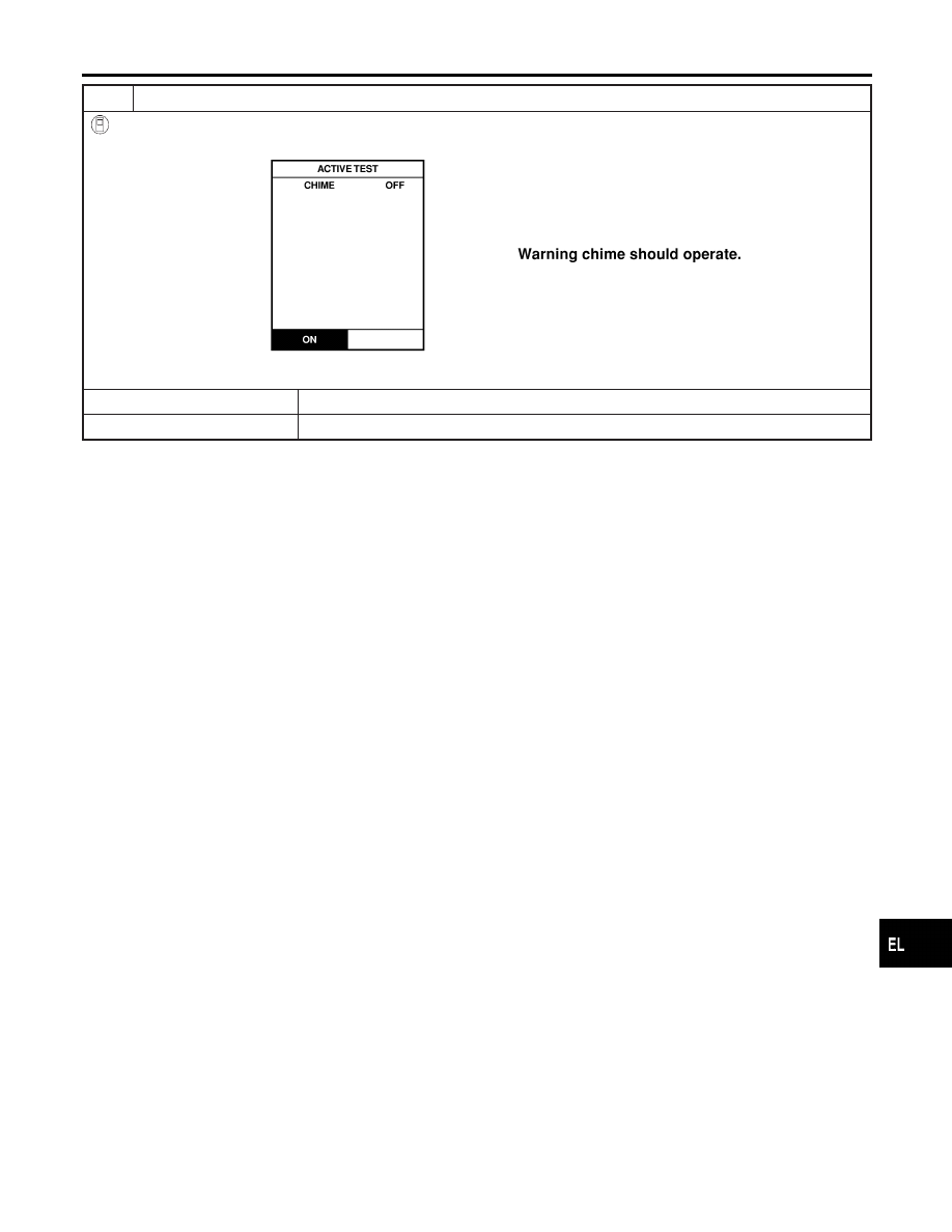
CHECK WARNING CHIME
With CONSULT-II
Perform “CHIME” in “ACTIVE TEST” mode with CONSULT-II.
SEL320W
OK or NG
OK
©
System is OK.
NG
©
Replace smart entrance control unit.
GI
MA
EM
LC
EC
FE
AT
AX
SU
BR
ST
RS
BT
HA
SC
IDX
WARNING CHIME
Trouble Diagnoses (Cont’d)
EL-189