Infiniti I30 (A33). Manual - part 304
 

  Index      Infiniti     Infiniti I30 (A33) - service repair manual 2001 year


Search            


Content   ..  302  303  304  305   ..


Infiniti I30 (A33). Manual - part 304


On Board Diagnosis Logic

NHEC0316

NOTE:
If DTC P1440 is displayed with P1448, perform trouble diagno-
sis for DTC P1448 first. (See EC-564.)
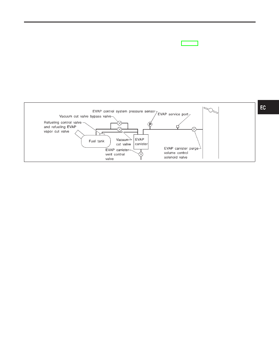
This diagnosis detects leaks in the EVAP purge line using of vapor
pressure in the fuel tank.
The EVAP canister vent control valve is closed to shut the EVAP
purge line. The vacuum cut valve bypass valve will then be opened
to clear the line between the fuel tank and the EVAP canister purge
volume control solenoid valve. The EVAP control system pressure
sensor can now monitor the pressure inside the fuel tank.
If pressure increases, the ECM will check for leaks in the line
between the vacuum cut valve and EVAP canister purge volume
control solenoid valve.

SEF323U

Malfunction is detected when EVAP control system has a leak,
EVAP control system does not operate properly.

CAUTION:

I

Use only a genuine NISSAN fuel filler cap as a replace-
ment. If an incorrect fuel filler cap is used, the MIL may
come on.

I

If the fuel filler cap is not tightened properly, the MIL may
come on.

I

Use only a genuine NISSAN rubber tube as a replacement.

Possible Cause

NHEC0587

I

Incorrect fuel tank vacuum relief valve

I

Incorrect fuel filler cap used

I

Fuel filler cap remains open or fails to close.

I

Foreign matter caught in fuel filler cap.

I

Leak is in line between intake manifold and EVAP canister
purge volume control solenoid valve.

I

Foreign matter caught in EVAP canister vent control valve.

I

EVAP canister or fuel tank leaks

I

EVAP purge line (pipe and rubber tube) leaks

GI

MA

EM

LC

FE

AT

AX

SU

BR

ST

RS

BT

HA

SC

EL

IDX

DTC P1440 EVAP CONTROL SYSTEM (SMALL LEAK) (POSITIVE PRESSURE)

On Board Diagnosis Logic

EC-531

I

EVAP purge line rubber tube bent.

I

Blocked or bent rubber tube to EVAP control system pressure
sensor

I

Loose or disconnected rubber tube

I

EVAP canister vent control valve and the circuit

I

EVAP canister purge volume control solenoid valve

I

Absolute pressure sensor

I

Fuel tank temperature sensor

I

O-ring of EVAP canister vent control valve is missing or dam-
aged.

I

Water separator

I

EVAP canister is saturated with water.

I

Fuel level sensor and the circuit

I

EVAP control system pressure sensor

I

Refueling control valve

I

ORVR system leaks

DTC Confirmation Procedure

NHEC0317

Refer to “P0440 EVAP CONTROL SYSTEM (SMALL LEAK)
(NEGATIVE PRESSURE)”, EC-362.

Diagnostic Procedure

NHEC0643

Refer to “P0440 EVAP CONTROL SYSTEM (SMALL LEAK)
(NEGATIVE PRESSURE)”, EC-362.

DTC P1440 EVAP CONTROL SYSTEM (SMALL LEAK) (POSITIVE PRESSURE)

Possible Cause (Cont’d)

EC-532

Description

NHEC0319

SYSTEM DESCRIPTION

NHEC0319S01

Sensor

Input Signal to ECM

ECM

function

Actuator

Crankshaft position sensor (POS)

Engine speed (POS signal)

EVAP can-
ister purge
flow control

EVAP canister purge volume
control solenoid valve

Crankshaft position sensor (REF)

Engine speed (REF signal)

Mass air flow sensor

Amount of intake air

Engine coolant temperature sensor

Engine coolant temperature

Ignition switch

Start signal

Throttle position sensor

Throttle position

Throttle position switch

Closed throttle position

Heated oxygen sensors 1 (front)

Density of oxygen in exhaust gas
(Mixture ratio feedback signal)

Fuel tank temperature sensor

Fuel temperature in fuel tank

Vehicle speed sensor

Vehicle speed

This system controls flow rate of fuel vapor from the EVAP canis-
ter. The opening of the vapor by-pass passage in the EVAP canis-
ter purge volume control solenoid valve changes to control the flow
rate. The EVAP canister purge volume control solenoid valve
repeats ON/OFF operation according to the signal sent from the
ECM. The opening of the valve varies for optimum engine control.
The optimum value stored in the ECM is determined by consider-
ing various engine conditions. When the engine is operating, the
flow rate of fuel vapor from the EVAP canister is regulated as the
air flow changes.

SEF337U

COMPONENT DESCRIPTION

NHEC0319S02

The EVAP canister purge volume control solenoid valve uses a
ON/OFF duty to control the flow rate of fuel vapor from the EVAP
canister. The EVAP canister purge volume control solenoid valve
is moved by ON/OFF pulses from the ECM. The longer the ON
pulse, the greater the amount of fuel vapor that will flow through the
valve.

CONSULT-II Reference Value in Data Monitor
Mode

NHEC0320

Specification data are reference values.

MONITOR ITEM

CONDITION

SPECIFICATION

PURG VOL C/V

I

Engine: After warming up

I

Air conditioner switch “OFF”

I

Shift lever: “N”

I

No-load

Idle (Vehicle stopped)

0%

2,000 rpm

GI

MA

EM

LC

FE

AT

AX

SU

BR

ST

RS

BT

HA

SC

EL

IDX

DTC P1444 EVAP CANISTER PURGE VOLUME CONTROL SOLENOID VALVE

Description

EC-533

On Board Diagnosis Logic

NHEC0322

Malfunction is detected when the canister purge flow is detected
during the specified driving conditions, even when EVAP canister
purge volume control solenoid valve is completely closed.

Possible Cause

NHEC0588

I

EVAP control system pressure sensor

I

EVAP canister purge volume control solenoid valve (The valve
is stuck open.)

I

EVAP canister vent control valve

I

EVAP canister

I

Hoses
(Hoses are connected incorrectly or clogged.)

DTC Confirmation Procedure

NHEC0323

NOTE:
If “DTC Confirmation Procedure” has been previously conducted,
always turn ignition switch “OFF” and wait at least 10 seconds
before conducting the next test.
TESTING CONDITION:
Always perform test at a temperature of 5°C (41°F) or more.

DTC P1444 EVAP CANISTER PURGE VOLUME CONTROL SOLENOID VALVE

On Board Diagnosis Logic

EC-534


Content   ..  302  303  304  305   ..