Infiniti I30 (A33). Manual - part 288
11
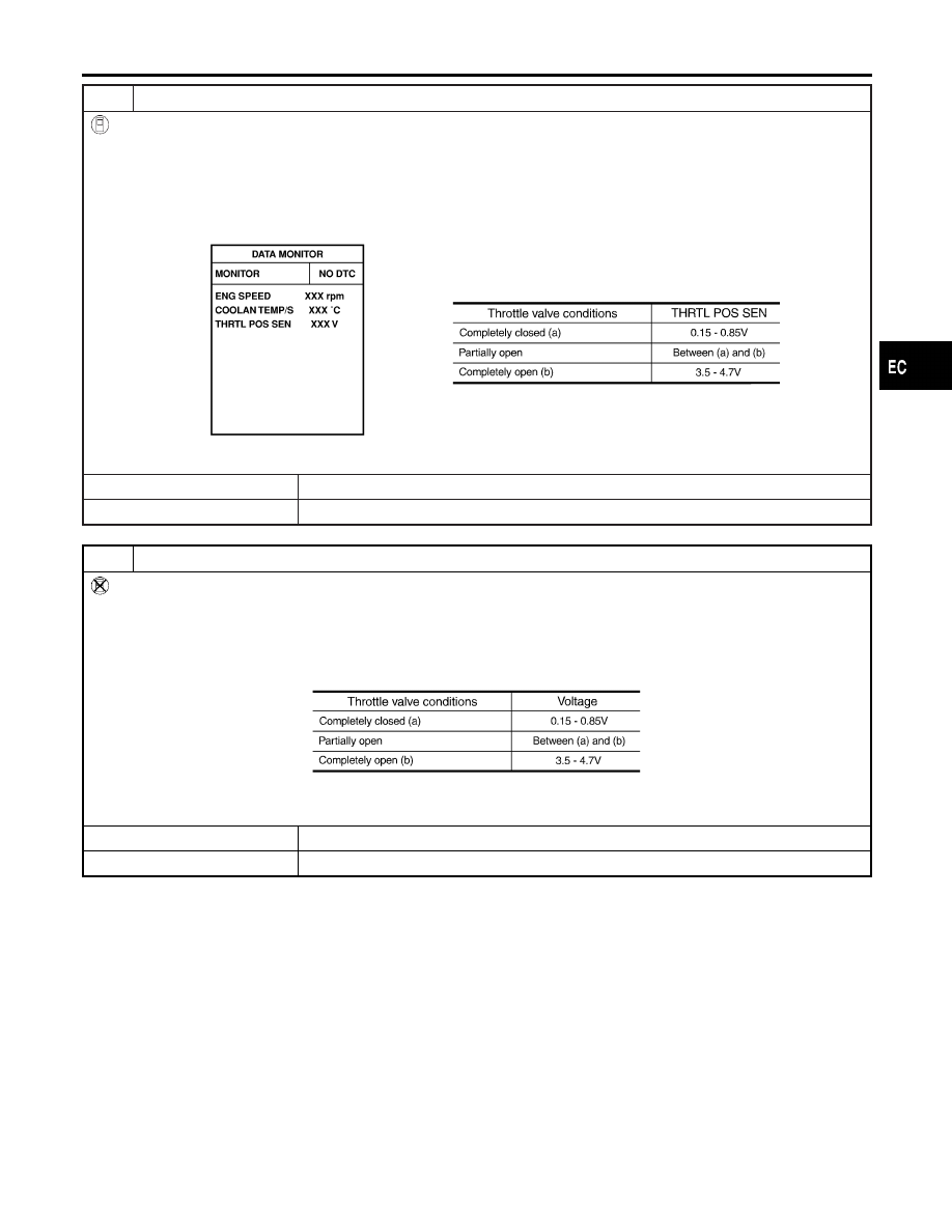
CHECK THROTTLE POSITION SENSOR
With CONSULT-II
1. Start engine and warm it up to normal operating temperature.
2. Stop engine (ignition switch OFF).
3. Turn ignition switch ON.
4. Select “DATA MONITOR” mode with CONSULT-II.
5. Check voltage of “THRTL POS SEN” under the following conditions.
Voltage measurement must be made with throttle position sensor installed in vehicle.
SEF062Y
OK or NG
OK
©
GO TO 14.
NG
©
GO TO 13.
12
CHECK THROTTLE POSITION SENSOR
Without CONSULT-II
1. Start engine and warm it up to normal operating temperature.
2. Stop engine (ignition switch OFF).
3. Turn ignition switch ON.
4. Check voltage between ECM terminal 91 (Throttle position sensor signal) and ground.
Voltage measurement must be made with throttle position sensor installed in vehicle.
MTBL0231
OK or NG
OK
©
GO TO 14.
NG
©
GO TO 13.
GI
MA
EM
LC
FE
AT
AX
SU
BR
ST
RS
BT
HA
SC
EL
IDX
DTC P1130 SWIRL CONTROL VALVE CONTROL SOLENOID VALVE
Diagnostic Procedure (Cont’d)
EC-467