Infiniti I30 (A33). Manual - part 123


  Index      Infiniti     Infiniti I30 (A33) - service repair manual 2001 year


Search            


Content   ..  121  122  123  124   ..


Infiniti I30 (A33). Manual - part 123


NOTE:
Stopping distance may be longer than vehicles without ABS when
road condition is slippery.

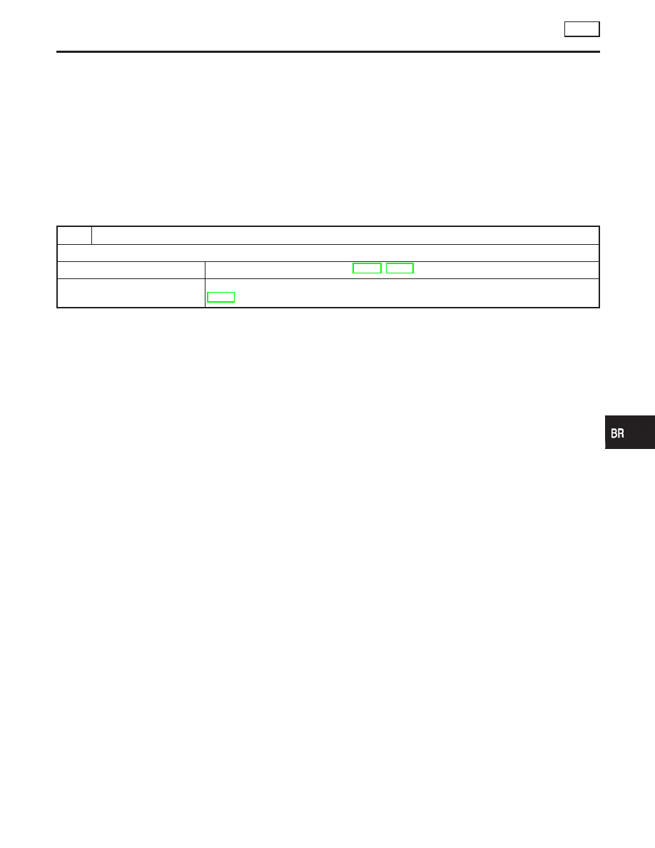
4. ABS Does Not Work

NHBR0123

1

CHECK WARNING LAMP INDICATION

Does the ABS warning lamp activate?

Yes

©

Carry out self-diagnosis. Refer to BR-48, BR-50.

No

©

Go to “3. CHECK WARNING LAMP INDICATION” in “2. Unexpected Pedal Action”,
BR-73.

NOTE:
ABS does not work when vehicle speed is under 10 km/h (6 MPH).

GI

MA

EM

LC

EC

FE

AT

AX

SU

ST

RS

BT

HA

SC

EL

IDX

TROUBLE DIAGNOSES FOR SYMPTOMS

ABS

3. Long Stopping Distance (Cont’d)

BR-75

5. Pedal Vibration and Noise

=NHBR0124

1

INSPECTION START

Pedal vibration and noise inspection

SAT797A

©

GO TO 2.

2

CHECK SYMPTOM

1. Apply brake.
2. Start engine.

Does the symptom appear only when engine is started?

Yes

©

Carry out self-diagnosis. Refer to BR-48, BR-50.

No

©

GO TO 3.

3

RECHECK SYMPTOM

Does the symptom appear when electrical equipment switches (such as headlamp) are operated?

Yes

©

INSPECTION END

No

©

Go to “3. CHECK WARNING LAMP INDICATION” in “2. Unexpected Pedal Action”,
BR-73.

NOTE:
ABS may operate and cause vibration under any of the following
conditions.

I

Applying brake gradually when shifting or operating clutch.

I

Low friction (slippery) road.

I

High speed cornering.

I

Driving over bumps and pot holes.

I

Engine speed is over 5,000 rpm with vehicle stopped.

TROUBLE DIAGNOSES FOR SYMPTOMS

ABS

5. Pedal Vibration and Noise

BR-76

6. ABS Warning Lamp Does Not Come On
When Ignition Switch Is Turned On

=NHBR0125

1

INSPECTION START

Warning lamp circuit inspection

SBR598E

©

GO TO 2.

2

CHECK FUSE

Check 10A fuse No. 30 for warning lamp. For fuse layout, refer to “POWER SUPPLY ROUTING” in EL section.

Is fuse OK?

Yes

©

GO TO 3.

No

©

Replace fuse.

3

CHECK ABS CONTROL UNIT POWER SUPPLY CIRCUIT

1. Install 10A fuse.
2. Remove solenoid valve relay.
3. Disconnect connectors from control unit and actuator.
4. Check voltage between control unit connector terminal 2 and ground after turning ignition switch “ON”.

SBR599E

Does battery voltage exist after turning ignition switch “ON”?

Yes

©

GO TO 5.

No

©

GO TO 4.

GI

MA

EM

LC

EC

FE

AT

AX

SU

ST

RS

BT

HA

SC

EL

IDX

TROUBLE DIAGNOSES FOR SYMPTOMS

ABS

6. ABS Warning Lamp Does Not Come On When Ignition Switch Is Turned On

BR-77

4

CHECK WARNING LAMP INDICATION

Disconnect ABS actuator and electric unit connector.

SBR588E

Does the ABS warning lamp activate?

Yes

©

GO TO 6.

No

©

GO TO 5.

5

CHECK HARNESS FOR SHORT

1. Disconnect ABS actuator and electric unit connector.
2. Check voltage between ABS actuator and electric unit connector terminal 2 and ground.

SBR600E

Does battery voltage exist?

Yes

©

Check combination meter. Refer to WARNING LAMPS in EL section.

No

©

Repair harness and connectors between fuse and ABS actuator and electric unit connec-
tor terminal 2.

6

CHECK HARNESS CONNECTOR

Check ABS actuator and electric unit pin terminals for damage or connection of ABS actuator and electric unit harness
connector. Reconnect ABS actuator and electric unit harness connector. Then reset.

OK

©

INSPECTION END

NG

©

Replace ABS actuator and electric unit.

TROUBLE DIAGNOSES FOR SYMPTOMS

ABS

6. ABS Warning Lamp Does Not Come On When Ignition Switch Is Turned On (Cont’d)

BR-78


Content   ..  121  122  123  124   ..