Infiniti G35 (V35). Manual - part 65
TRANSMISSION ASSEMBLY
AT-251
D
E
F
G
H
I
J
K
L
M
A
B
AT
TRANSMISSION ASSEMBLY
PFP:31020
Removal and Installation
NCS000J0
REMOVAL
CAUTION:
●
When removing the A/T assembly from engine, first remove the crankshaft position sensor (POS)
from the A/T assembly.
●
Be careful not to damage sensor edge.
1.
Disconnect the battery cable from the negative terminal.
2.
Remove engine cover.
3.
Remove A/T fluid level gauge.
4.
Remove engine under cover with power tool.
5.
Remove front cross bar with power tool. Refer to
6.
Remove exhaust front tube and center muffler with power tool.
Refer to
EX-3, "Removal and Installation"
7.
Remove three way catalyst. Refer to
.
8.
Remove rear propeller shaft. Refer to
.
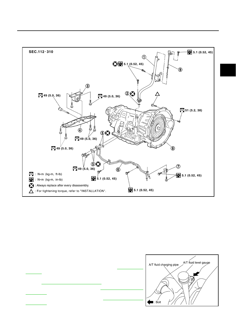
1.
A/T fluid charging pipe
2.
O-ring
3.
Engine mounting insulator (rear)
4.
Rear engine mounting member
5.
Copper washer
6.
Fluid cooler tube
7.
Bracket
8.
A/T assembly
9.
A/T fluid level gauge
SCIA6378E
SCIA4738E