Infiniti G35 (V35). Manual - part 64
ON-VEHICLE SERVICE
AT-247
D
E
F
G
H
I
J
K
L
M
A
B
AT
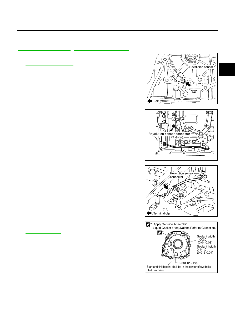
INSTALLATION
CAUTION:
After completing installation, check A/T position, A/T fluid leakage and A/T fluid level. Refer to
1.
Install revolution sensor in transmission case, and then tighten
revolution sensor mounting bolt to the specified torque. Refer to
.
CAUTION:
●
Do not subject it to impact by dropping or hitting it.
●
Do not disassemble.
●
Do not allow metal filings, etc. to get on the sensor's front
edge magnetic area.
●
Do not place in an area affected by magnetism.
2.
Connect revolution sensor connector.
3.
Securely fasten revolution sensor harness with clip.
4.
Apply recommended sealant (Genuine Anaerobic Liquid Gasket
or equivalent. Refer to
GI-46, "Recommended Chemical Prod-
.) to rear extension assembly as shown in
the figure.
CAUTION:
Completely remove all moisture, oil and old sealant, etc.
from transmission case and rear extension assembly
mounting surfaces.
SCIA3997E
SCIA7524E
SCIA7525E
SCIA8228E