Infiniti G35 (V35). Manual - part 28
 

  Index      Infiniti     Infiniti G35 (V35) Coupe - service repair manual 2007 year


Search            


Content   ..  26  27  28  29   ..


Infiniti G35 (V35). Manual - part 28


DTC P0615 START SIGNAL CIRCUIT

AT-103

D

E

F

G

H

I

J

K

L

M

A

B

AT

TCM terminals and data are reference value. Measured between each terminal and ground.

Diagnostic Procedure

NCS000CK

1. 

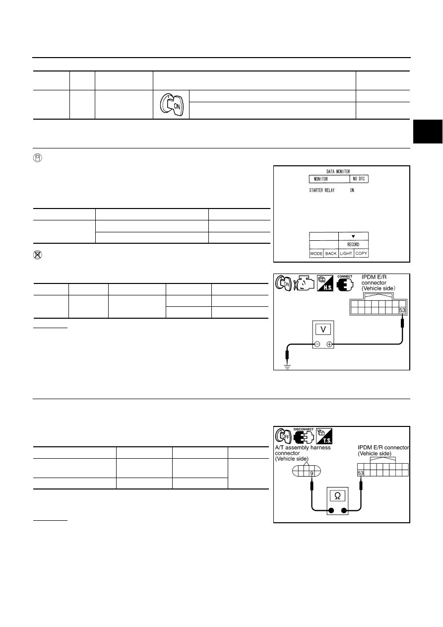
CHECK STARTER RELAY

 With CONSULT-II

1.

Turn ignition switch ON.

2.

Select “SELECTION FROM MENU” in “DATA MONITOR” mode
for “A/T” with CONSULT-II and check monitor “STARTER
RELAY” ON/OFF.

 Without CONSULT-II

1.

Turn ignition switch ON.

2.

Check voltage between the IPDM E/R connector and ground.

OK or NG

OK

>> GO TO 5.

NG

>> GO TO 2.

2. 

 CHECK HARNESS BETWEEN A/T ASSEMBLY HARNESS CONNECTOR AND IPDM E/R CONNEC-

TOR

1.

Turn ignition switch OFF.

2.

Disconnect A/T assembly harness connector and IPDM E/R connector.

3.

Check continuity between A/T assembly harness connector and
IPDM E/R connector.

4.

If OK, check harness for short to ground and short to power.

5.

Reinstall any part removed.

OK or NG

OK

>> GO TO 3.

NG

>> Repair open circuit or short to ground or short to power in harness or connectors.

Terminal

Wire 

color

Item

Condition

Data (Approx.)

9

GY/R

Starter  relay

Selector lever in “N” and “P” positions.

Battery voltage

Selector lever in other positions.

0 V

Item name

Condition 

Display value

STARTER RELAY

Selector lever in “N” and “P” positions.

ON

Selector lever in other positions.

OFF

Item

Connector

Terminal

Shift position

Voltage (Approx.) 

Starter 
relay

E9

53 - Ground

“N” and “P”

Battery voltage

“R” and “D”

0 V

PCIA0056E

SCIA2103E

Item

 Connector

Terminal

Continuity

A/T assembly harness con-
nector

F40

9

Yes

IPDM E/R connector

E9

53

SCIA5439E

AT-104

DTC P0615 START SIGNAL CIRCUIT

3. 

CHECK TERMINAL CORD ASSEMBLY

1.

Remove control valve with TCM. Refer to 

AT-225, "Control Valve with TCM and A/T Fluid Temperature

Sensor 2"

 .

2.

Disconnect A/T assembly harness connector and TCM connector.

3.

Check continuity between A/T assembly harness connector ter-
minal and TCM connector terminal.

4.

If OK, check harness for short to ground and short to power.

5.

Reinstall any part removed.

OK or NG

OK

>> GO TO 4.

NG

>> Replace open circuit or short to ground and short to power in harness or connectors.

4. 

DETECT MALFUNCTIONING ITEM

Check the following.

Starter relay, Refer to 

SC-10, "STARTING SYSTEM"

 .

IPDM E/R, Refer to 

PG-16, "IPDM E/R (INTELLIGENT POWER DISTRIBUTION MODULE ENGINE

ROOM)"

 .

OK or NG

OK

>> Replace control valve with TCM. Refer to 

AT-225, "Control Valve with TCM and A/T Fluid Temper-

ature Sensor 2"

 .

NG

>> Repair or replace damaged parts.

5. 

CHECK DTC

Perform 

AT-101, "DTC Confirmation Procedure"

 .

OK or NG

OK

>> INSPECTION END

NG

>> GO TO 2.

Item

 Connector

Terminal

Continuity

A/T assembly harness con-
nector

F40

9

Yes

TCM connector 

F502

SCIA5440E

DTC P0700 TCM

AT-105

D

E

F

G

H

I

J

K

L

M

A

B

AT

DTC P0700 TCM

PFP:31036

Description

NCS000CL

The TCM consists of a microcomputer and connectors for signal input and output and for power supply. The
TCM controls the A/T.

On Board Diagnosis Logic

NCS000CM

This is an OBD-II self-diagnostic item. 

Diagnostic trouble code “P0700 TCM” with CONSULT-II is detected when TCM is malfunctioning.

Possible Cause

NCS000CN

TCM.

DTC Confirmation Procedure

NCS000CO

NOTE:
If “DTC Confirmation Procedure” has been previously performed, always turn ignition switch OFF and
wait at least 10 seconds before performing the next test.
After the repair, perform the following procedure to confirm the malfunction is eliminated.

 WITH CONSULT-II

1.

Turn ignition switch ON.

2.

Select “ECU INPUT SIGNALS” or “MAIN SIGNALS” in “DATA
MONITOR” mode for “A/T” with CONSULT-II.

3.

Touch “START”.

4.

Start engine.

5.

Run engine for at least 2 consecutive seconds at idle speed.

6.

If DTC is detected, go to 

AT-105, "Diagnostic Procedure"

 .

 WITH GST

Follow the procedure “WITH CONSULT-II”.

Diagnostic Procedure

NCS000CP

1. 

CHECK DTC

 With CONSULT-II

1.

Turn ignition switch ON.

2.

Select “SELF DIAG RESULTS” mode for “A/T” with CONSULT-II.

3.

Touch “ERASE”.

4.

Turn ignition switch “OFF” and wait at least 10 seconds.

5.

Perform “DTC Confirmation Procedure”. Refer to 

AT-105, "DTC Confirmation Procedure"

 .

Is the “P0700 TCM” displayed again?

YES

>> Replace the control valve with TCM. Refer to 

AT-225, "Control Valve with TCM and A/T Fluid Tem-

perature Sensor 2"

 .

NO

>> INSPECTION END

BCIA0031E

AT-106

DTC P0705 PARK/NEUTRAL POSITION SWITCH

DTC P0705 PARK/NEUTRAL POSITION SWITCH

PFP:32006

Description

NCS000CQ

The PNP switch includes a transmission range switch.

The transmission range switch detects the selector lever position and sends a signal to the TCM.

CONSULT-II Reference Value

NCS000CR

On Board Diagnosis Logic

NCS000CS

This is an OBD-II self-diagnostic item.

Diagnostic trouble code “P0705 PNP SW/CIRC” with CONSULT-II or 9th judgment flicker without CON-
SULT-II is detected under the following conditions.

When TCM does not receive the correct voltage signal from the PNP switches 1, 2, 3 and 4 based on the
gear position.

When no other position but “P” position is detected from “N” positions.

Possible Cause

NCS000CT

Harness or connectors.
(PNP switches 1, 2, 3 and 4 and TCM circuit is open or shorted.)

PNP switches 1, 2, 3 and 4.

DTC Confirmation Procedure

NCS000CU

CAUTION:

Always drive vehicle at a safe speed.
NOTE:
If “DTC Confirmation Procedure” has been previously performed, always turn ignition switch OFF and
wait at least 10 seconds before performing the next test.
After the repair, perform the following procedure to confirm the malfunction is eliminated.

 WITH CONSULT-II

1.

Turn ignition switch ON. 

2.

Select “ECU INPUT SIGNALS” or “MAIN SIGNALS” in “DATA
MONITOR” mode for “A/T” with CONSULT-II.

3.

Touch “START”.

4.

Start engine.

5.

Drive vehicle and maintain the following conditions for at least 2
consecutive seconds.
ACCELE POSI: More than 1.0/8

6.

If DTC is detected, go to 

AT-108, "Diagnostic Procedure"

 .

 WITH GST

Follow the procedure “WITH CONSULT-II”.

Item name

Condition 

Display value

SLCT LVR POSI

Selector lever in “N” and “P” positions.

N/P

Selector lever in “R” position.

R

Selector lever in “D” position.

D

BCIA0031E


Content   ..  26  27  28  29   ..