Hyundai Elantra (2025 year). Manual in english - page 4
Emergency situations
If your vehicle does not start after a few
Tire Pressure Monitoring
attempts, it probably requires service.
Have your vehicle inspected by an
System (TPMS)
authorized HYUNDAI dealer.
Disconnect the jumper cables in the exact
reverse order you connected them:
1. Disconnect the jumper cable from the
chassis ground of your vehicle (4).
2. Disconnect the other end of the jumper
cable from the black, negative (-)
battery/jumper terminal of the
assisting vehicle (3).
3. Disconnect the second jumper cable
from the red, positive (+)
battery/jumper terminal of the
assisting vehicle (2).
4. Disconnect the other end of the jumper
cable from the red, positive (+) battery
terminal of your vehicle (1).
Information
An inappropriately disposed battery may
be harmful to the environment and
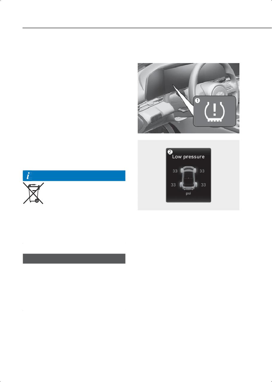
(1) Low Tire Pressure Telltale/TPMS
human health. Always dispose of a used
Malfunction Indicator
battery according to your local law(s) or
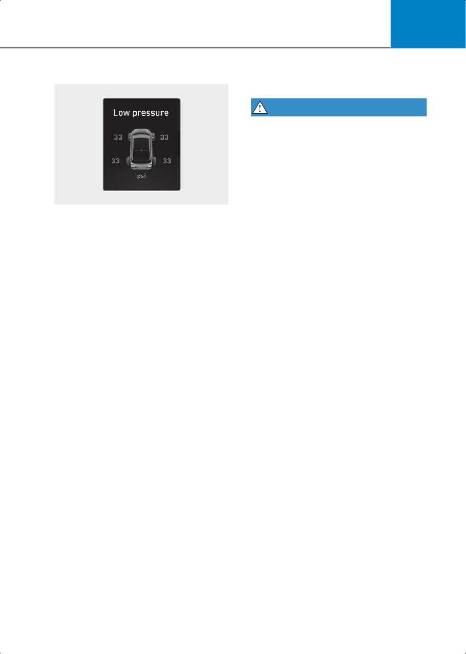
(2) Low Tire Pressure Position Telltale and
regulations.
Tire Pressure Telltale (Shown on the
cluster display)
NOTICE
To prevent damage to your vehicle:
• Only use a 12 V power supply (battery or
jumper system) to jump start your
vehicle.
• Do not attempt to jump start your
vehicle by push-starting.
8-4
8
Check tire pressure
Tire pressure monitoring
system
WARNING
Over-inflation or under-inflation can
reduce tire life, adversely affect vehicle
handling, and lead to sudden tire failure
that may cause loss of vehicle control
resulting in an collision.
Each tire, including the spare (if
provided), should be checked monthly
when cold and inflated to the inflation
pressure recommended by the vehicle
•
You can check the tire pressure in the
manufacturer on the vehicle placard or
Driving Assist mode in the instrument
tire inflation pressure label. (If your
cluster.
vehicle has tires of a different size than
Refer to the "View modes" in the
the size indicated on the vehicle placard
complete Owner's Manual.
or tire inflation pressure label, you should
determine the proper tire inflation
•
Tire pressure appears after a few
pressure for those tires.)
minutes of driving. If the tire pressure
does not appear when the vehicle is
As an added safety feature, your vehicle
stopped, the message, "Drive to
has been equipped with a tire pressure
display" appears.
monitoring system (TPMS) that
illuminates a low tire pressure telltale
•
The displayed tire pressure values may
when one or more of your tires is
differ from those measured with a tire
significantly under-inflated. Accordingly,
pressure gauge.
when the low tire pressure telltale
•
You can change the tire pressure unit
illuminates, you should stop and check
from the Settings menu in the
your tires as soon as possible, and inflate
instrument cluster or infotainment
them to the proper pressure. Driving on a
system. Select:
significantly under-inflated tire causes
- User Settings > Units > Tire Pressure
the tire to overheat and can lead to tire
Unit > psi, kpa, bar (for instrument
failure.
cluster)
Under-inflation also reduces fuel
- Settings > General > Units > Tire
efficiency and tire tread life, and may
Pressure Unit > psi, kpa, bar (for
affect the vehicle’s handling and stopping
infotainment system)
ability.
Please note that the TPMS is not a
substitute for proper tire maintenance,
and it is the driver’s responsibility to
maintain correct tire pressure, even if
under-inflation has not reached the level
to trigger illumination of the TPMS low
tire pressure telltale.
8-5
Emergency situations
Your vehicle has also been equipped with
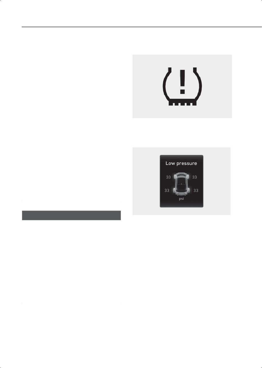
Low tire pressure warning
a TPMS malfunction indicator to indicate
light
when the system is not operating
properly. The TPMS malfunction indicator
is combined with the low tire pressure
telltale. When the system detects a
malfunction, the telltale flashes for
approximately one minute and then
remains continuously illuminated. This
sequence continues upon subsequent
vehicle start-ups as long as the
malfunction exists.
When the malfunction indicator is
illuminated, the system may not be able
to detect or signal low tire pressure as
intended. TPMS malfunctions may occur
Low tire pressure position and
for a variety of reasons, including the
tire pressure telltale
installation of replacement or alternate
tires or wheels on the vehicle that prevent
the TPMS from functioning properly.
Always check the TPMS malfunction
telltale after replacing one or more tires or
wheels on your vehicle to ensure that the
replacement or alternate tires and wheels
allow the TPMS to continue to function
properly.
NOTICE
Have the system inspected by an
TPMS is not a substitute for manually
authorized HYUNDAI dealer if:
checking the tire pressure with a tire
gauge. Changes in temperature affect tire
1. The Low Tire Pressure Telltale/TPMS
pressure. Refer to "Check tire pressure" in
Malfunction Indicator does not
the Maintenance chapter for proper tire
illuminate for 3 seconds when the
inflation and tire pressure measurement
ignition switch is moved to the ON
procedure.
position or the engine is running.
When the tire pressure monitoring
2. The TPMS Malfunction Indicator
system warning indicators illuminate and
remains illuminated after blinking for
a warning message appears on the cluster
about 1 minute.
display, one or more of your tires are
3. The Low Tire Pressure Position Telltale
significantly under-inflated. The Low Tire
remains illuminated.
Pressure Position Telltale indicates which
tire is significantly under-inflated by
illuminating the corresponding position
light.
8-6
8
If either telltale illuminates, immediately
WARNING
reduce the vehicle speed, avoid hard
cornering and anticipate increased
Low pressure damage
stopping distances. Stop and check your
Significantly low tire pressure makes the
tires as soon as possible. Inflate the tires
vehicle unstable and may contribute to
to the proper pressure as indicated on the
loss of vehicle control and increased
vehicle’s placard or tire inflation pressure
braking distances.
label located on the driver’s side center
pillar outer panel.
Continued driving on low pressure tires
may cause the tires to overheat and fail.
If you cannot reach a service station or
the tire cannot hold the newly added air,
replace the low pressure tire with the
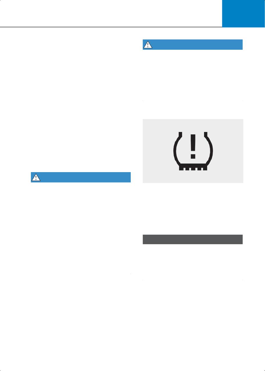
TPMS malfunction indicator
spare tire.
The Low Tire Pressure Telltale remains on
and the TPMS Malfunction Indicator may
blink for one minute and then remain
illuminated (when the vehicle is driven
about 10 minutes at the speed above 15.5
mph (25 km/h)) until you have the low
pressure tire repaired and replaced on the
vehicle.
WARNING
In winter or cold weather, the Low Tire
The TPMS Malfunction Indicator
Pressure Telltale may be illuminated if the
illuminates after it blinks for about one
tire pressure was adjusted to the
minute when there is a problem with the
recommended tire inflation pressure in
Tire Pressure Monitoring System.
warm weather. It does not mean your
TPMS is malfunctioning because the
Have the system inspected by an
decreased temperature leads to a
authorized HYUNDAI dealer as soon as
proportional lowering of tire pressure.
possible.
When you drive your vehicle from a warm
NOTICE
area to a cold area or from a cold area to a
warm area, or the outside temperature is
If there is a malfunction with the TPMS,
greatly higher or lower, check the tire
the individual tire pressures on the cluster
inflation pressure and adjust the tires to
display are not be available. Have the
the recommended tire inflation pressure.
system inspected by an authorized
HYUNDAI dealer as soon as possible.
8-7
Emergency situations
Malfunction Indicator goes off within a
NOTICE
few minutes of driving.
The TPMS Malfunction Indicator may
If the indicators do not turn off after a few
illuminate after blinking for one minute if
minutes, visit an authorized HYUNDAI
the vehicle is near electric power supply
dealer.
cables or radio transmitters such as police
Each wheel is equipped with a tire
stations, government and public offices,
pressure sensor mounted inside the tire
broadcasting stations, military
behind the valve stem (except for the
installations, airports, transmitting
spare tire). You must use TPMS specific
towers, etc.
wheels. It is recommended that you
Additionally, the TPMS Malfunction
always have your tires serviced by an
Indicator may illuminate if snow chains
authorized HYUNDAI dealer.
are used or if electronic devices such as
You may not be able to identify a tire with
computers, chargers, remote starters,
low pressure by simply looking at it.
navigation, etc. are near the vehicle. This
Always use a good quality tire pressure
may interfere with normal operation of
gauge to measure. Note that a tire that is
the TPMS.
hot (from being driven) has a higher
pressure measurement than a tire that is
cold.
Changing a tire with TPMS
A cold tire means the vehicle has been
If you have a flat tire, the Low Tire
sitting for 3 hours and driven for less than
Pressure and Position telltales come on.
1 mi. (1.6 km) in that 3 hour period.
Have the flat tire repaired by an
Allow the tire to cool before measuring
authorized HYUNDAI dealer as soon as
the inflation pressure. Always make sure
possible or replace the flat tire with the
the tire is cold before inflating to the
spare tire.
recommended pressure.
NOTICE
Do not use a puncture-repair kit not
approved by HYUNDAI. Tire sealant not
approved by HYUNDAI or the equivalent
sealant specified for your vehicle may
damage the tire pressure sensor.
The spare tire (if equipped) does not
come with a tire pressure monitoring
sensor. When the low pressure tire or the
flat tire is replaced with the spare tire, the
Low Tire Pressure Telltale remains on.
Also, the TPMS Malfunction Indicator
illuminates after blinking for one minute if
the vehicle is driven at the speed above
15.5 mph (25 km/h) for about 10 minutes.
Once the original wheel equipped with a
tire pressure monitoring sensor is
reinflated to the recommended pressure
and reinstalled on the vehicle, the Low
Tire Pressure Telltale and TPMS
8-8
8
If you have a flat tire (with
WARNING
• The TPMS cannot alert you to severe
spare tire)
and sudden tire damage caused by
if equipped
external factors such as nails or road
debris.
WARNING
• If you feel any vehicle instability,
Follow the instructions in this section
immediately take your foot off the
when replacing a tire to reduce the risk of
accelerator pedal, apply the brakes
serious injury or death. Changing a tire
gradually with light force, and slowly
can be dangerous.
move to a safe position off the road.
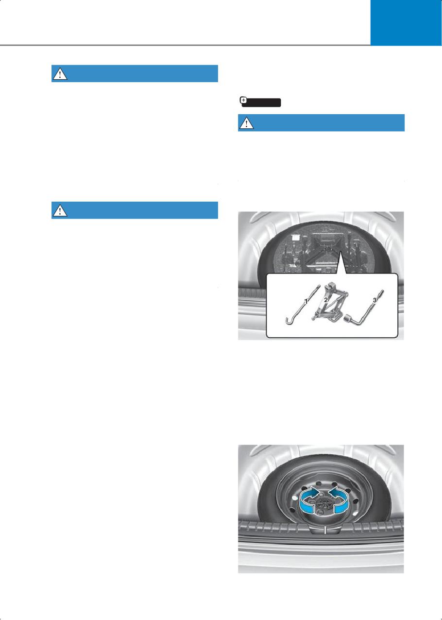
Jack and tools
WARNING
Tampering with, modifying, or disabling
the Tire Pressure Monitoring System
(TPMS) components may interfere with
the system’s ability to warn the driver of
low tire pressure conditions and/or TPMS
malfunctions and may void the warranty.
(1) Jack handle
(2) Jack
(3) Wheel lug wrench
The jack and wheel lug wrench are stored
in the cargo area under the luggage box
cover.
The jack is provided for emergency tire
changing only.
8-9
Emergency situations
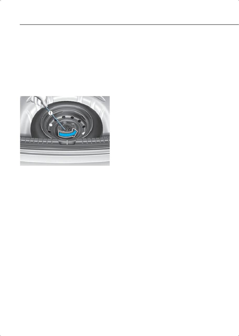
Turn the winged hold down bolt
counterclockwise to remove the spare
tire.
Store the spare tire in the same
compartment by turning the winged hold
down bolt clockwise.
To prevent the spare tire and tools from
"rattling", store them in their proper
locations.
If it is hard to loosen the tire hold down
wing bolt by hand, you can loosen it easily
using the jack handle.
1. Put the jack handle (1) inside of the tire
hold-down wing bolt.
2. Turn the tire hold-down wing bolt
counterclockwise with the jack handle.
8-10
8
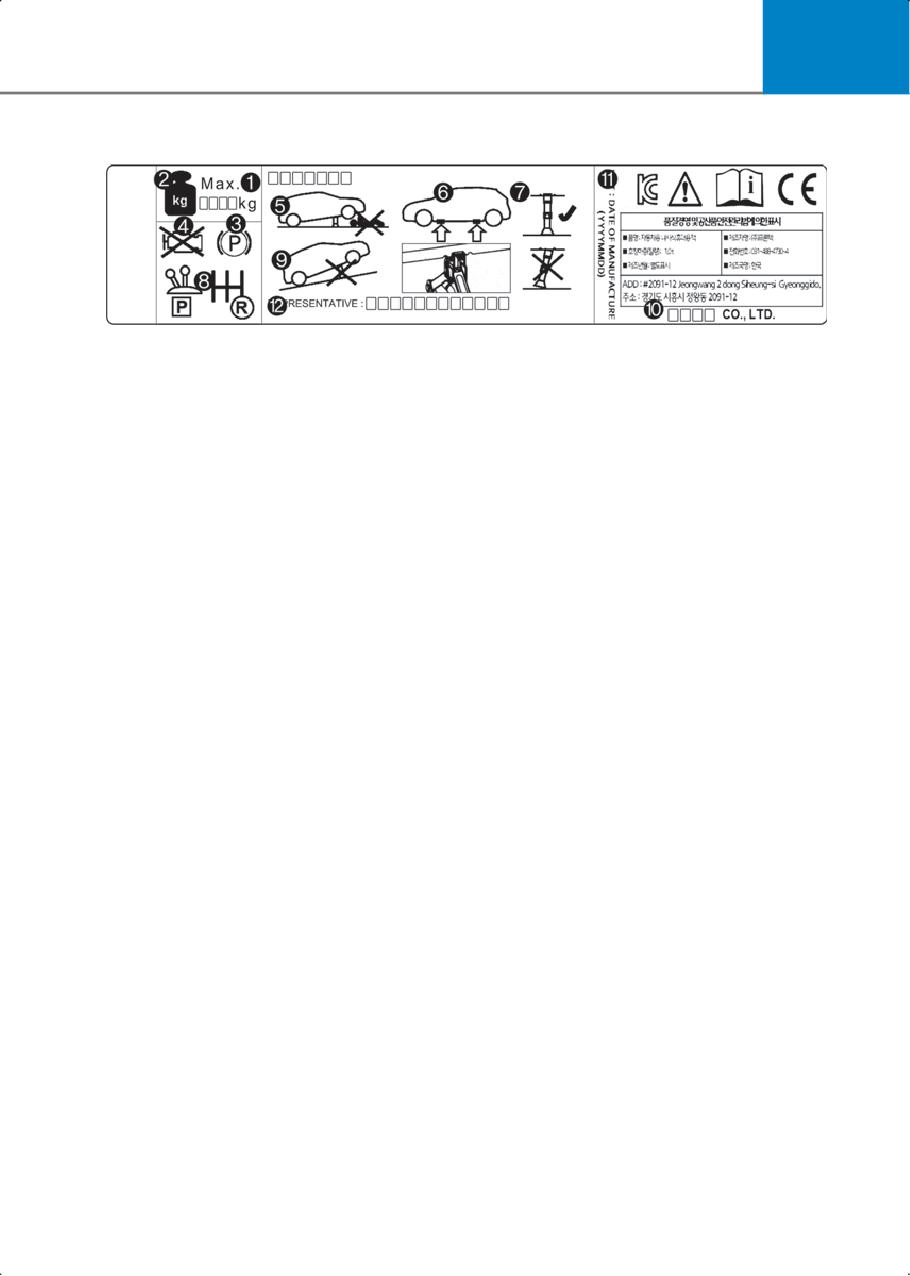
Jack label
The actual jack label in the vehicle may differ from the illustration.
For more detailed specifications, refer to the label attached to the jack.
1. Model Name
2. Maximum allowable load
3. Always apply the parking brake before using a jack.
4. Always turn off the engine before using a jack.
5. Never put any portion of your body under the vehicle supported by a jack.
6. Only use the designated jacking locations on the frame.
7. When supporting the vehicle, have the base plate of the jack flat on the ground under
the lifting point.
8. Shift to the P (Park) position with the gear.
9. Do not jack the vehicle on an incline. Only jack the vehicle on a firm level ground.
10.Jack manufacturer
11. Production date
12. Representative company and address
8-11
Emergency situations
Changing tires
WARNING
Because the vehicle may slip or roll off of
a jack causing serious injury or death, take
the following safety precautions:
• NEVER place any portion of your body
under the vehicle that is supported by a
jack.
• NEVER attempt to change a tire in the
lane of traffic. ALWAYS move the
vehicle completely off the road on a
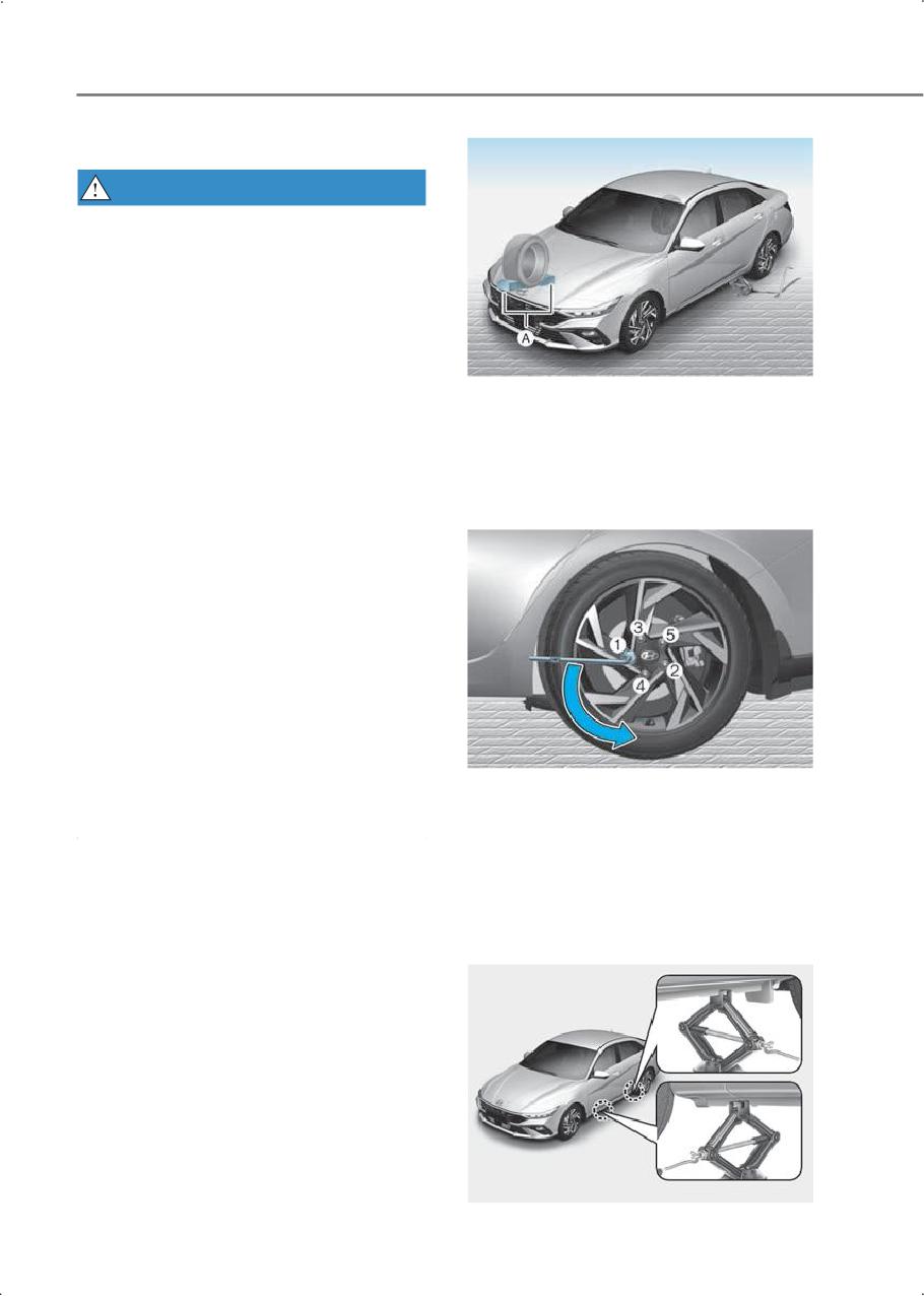
[A] Block
level, firm ground away from traffic
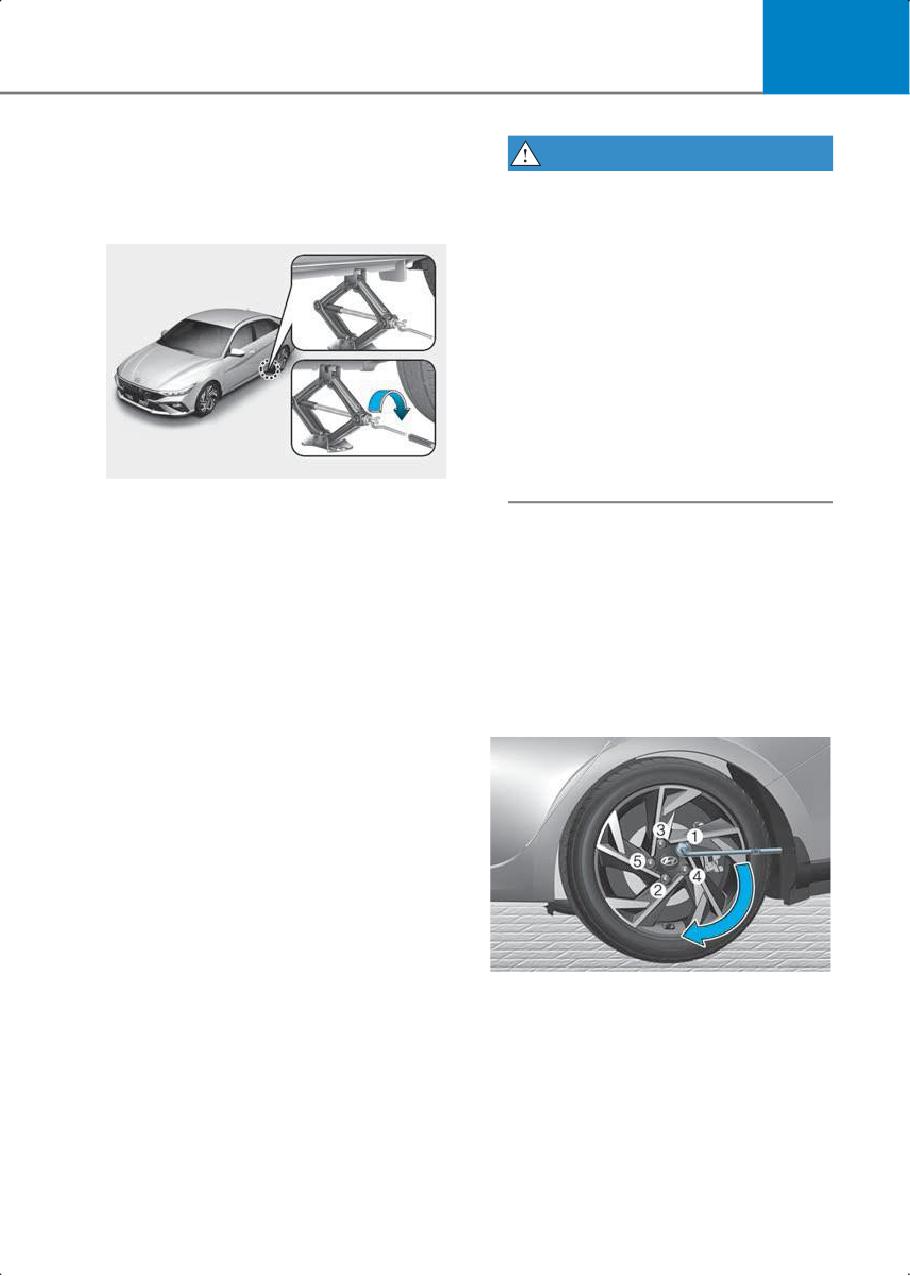
6. Loosen the wheel nuts
before trying to change a tire. If you
counterclockwise one turn each in the
cannot find a level, firm place off the
order shown above, but do not remove
road, call a towing service for
any wheel nuts until the tire has been
assistance.
raised off of the ground.
• ONLY use the jack provided with the
vehicle.
• ALWAYS place the jack on the
designated jacking positions on the
vehicle and NEVER on the bumpers or
any other part of the vehicle for jacking
support.
• Do not start or run the engine while the
vehicle is on the jack.
• Do not allow anyone to remain in the
vehicle while it is on the jack.
• Keep children away from the road and
7. Place the jack at the designated jacking
the vehicle.
position under the frame closest to the
tire you are changing. The jacking
positions are plates welded to the
Follow these steps to change your
frame with two notches. Never jack at
vehicle’s tire:
any other position or part of the vehicle
1. Park on a level, firm surface.
to prevent the vehicle slipping off of the
jack or damaging the vehicle.
2. Shift the gear to P (Park), apply the
parking brake, and move the ignition
switch to the LOCK/OFF position.
3. Press the hazard warning flasher
button.
4. Remove the wheel lug wrench, jack,
jack handle, and spare tire from the
vehicle.
5. Block both the front and rear of the tire
diagonally opposite of the tire you are
changing.
8-12
8
WARNING
8. Insert the jack handle into the jack and
turn it clockwise, raising the vehicle
Because the wheels may have sharp
until the tire clears the ground. Make
edges, handle them carefully to avoid
sure the vehicle is stable on the jack.
possible severe injury. Before putting
the wheel into place, make sure that
there is nothing on the hub or wheel
(such as mud, tar, gravel, etc.) that
interferes with the wheel from fitting
solidly against the hub.
If there is, remove it. If there is not good
contact on the mounting surface
between the wheel and hub, the wheel
nuts may come loose and cause the
loss of a wheel. Loss of a wheel may
result in loss of control of the vehicle.
This may cause serious injury or death.
9. Loosen the wheel nuts with the wheel
lug wrench and remove them with your
10. Install the spare tire onto the studs of
fingers. Remove the wheel from the
the hub.
studs and lay it flat on the ground out of
the way. Remove any dirt or debris from
11. Tighten the wheel nuts with your
the studs, mounting surfaces, and
fingers onto the studs with the smaller
spare tire.
end of the wheel nuts closest to the
wheel.
12. Lower the vehicle to the ground by
turning the jack handle
counterclockwise.
13. Use the wheel lug wrench to tighten
the wheel nuts in the order shown.
Double-check each wheel nuts until
they are tight. After changing tires,
have an authorized HYUNDAI dealer
tighten the wheel nuts to their proper
torque as soon as possible. Tighten the
wheel nuts to 79-94 lbf.ft (11-13 kgf.m).
8-13
Emergency situations
Check the tire pressure after installing the
WARNING
compact spare tire. The compact spare
tire should be inflated to 60 psi (420 kPa).
• Your vehicle has metric threads on the
If you have a tire gauge, check the spare
studs and wheel nuts. During tire
tire pressure (refer to the "Tires and
changing, make sure that the nuts that
Wheels" section in the complete Owner's
were removed are reinstalled. If you
Manual. for tire pressure instructions.). If
have to replace your wheel nuts, make
the spare tire pressure is lower or higher
sure they have metric threads to avoid
than the recommended, drive slowly to
damaging the studs and make sure the
the nearest service station and adjust to
wheel is properly secured to the hub.
the recommended pressure.
Contact an authorized HYUNDAI dealer
for assistance.
Always reinstall the valve cap after
checking or adjusting the tire pressure. If
• If the wheel studs are damaged, they
the cap is not replaced, air may leak from
may lose their ability to retain the
the tire. If you lose a valve cap, buy
wheel. This may cause loss of the wheel
another and install it as soon as possible.
and a collision resulting in serious
After changing tires, secure the flat tire
injuries.
and return the jack and tools to their
proper storage locations.
If any of the equipment such as jack,
NOTICE
wheel nuts, studs, or other equipment is
damaged or in poor condition, do not
Check the tire pressure as soon as
attempt to change the tire and call for
possible after installing a spare tire.
assistance.
Adjust it to the recommended pressure.
Use of compact spare tires
Compact spare tires are designed for
emergency use only. Drive carefully on
the compact spare tire and always follow
the safety precautions.
WARNING
To prevent compact spare tire failure and
loss of control possibly resulting in a
collision:
• Use the compact spare tire only in an
emergency.
• NEVER operate your vehicle over 50
mph (80 km/h).
• Do not exceed the vehicle’s maximum
load rating or the load carrying capacity
shown on the sidewall of the compact
spare tire.
• Do not use the compact spare tire
continuously. Repair or replace the
original tire as soon as possible to avoid
failure of the compact spare tire.
8-14
8
When driving on the compact spare tire
NOTICE
mounted to your vehicle:
• Do not take this vehicle through an
To prevent damaging the compact spare
automatic car wash after the compact
tire and your vehicle:
spare tire has been installed.
• Drive slowly enough for the road
• Do not use the compact spare tire on
conditions to avoid all hazards, such as
any other vehicle because this tire has
a potholes or debris.
been designed especially for your
• Avoid driving over obstacles. The
vehicle.
compact spare tire diameter is smaller
• The compact spare tire’s tread life is
than the diameter of a conventional tire
shorter than a regular tire. Inspect your
and reduces the ground clearance
compact spare tire regularly and
about 1 in. (25 mm).
replace worn compact spare tires with
• Do not use tire chains on the compact
the same size and design, mounted on
spare tire. Because of the smaller size, a
the same wheel.
tire chain will not fit properly.
• Do not use more than one compact
• Do not use the compact spare tire on
spare tire at a time.
any other wheels, nor should standard
• Do not tow a trailer while the compact
tires, snow tires, wheel covers or trim
spare tire is installed.
rings be used with the compact spare
wheel.
Information
• Do not suddenly accelerate or
decelerate (0 <-> 25 mph (0 <-> 40
When the original tire and wheel are
km/h)) in any driving mode. It may
repaired and reinstalled on the vehicle,
cause leakage of transfer oil.
the wheel nut torque must be set
correctly. The correct wheel nut
tightening torque is 79-94 lbf.ft (11-13
kgf.m).
8-15
Emergency situations
If you have a flat tire (with
Introduction
With the Tire Mobility Kit you stay mobile
Tire Mobility Kit)
even after experiencing a tire puncture.
if equipped
The compressor and sealing compound
system effectively and comfortably seals
most punctures in a passenger car tire
caused by nails or similar objects and
reinflates the tire.
After you ensure that the tire is properly
sealed you can drive cautiously on the tire
(distance up to 120 mi. (200 km)) at a max.
speed of 50 mph (80 km/h) in order to
reach a service station or tire dealer for
the tire replacement.
It is possible that some tires, especially
with larger punctures or damage to the
For safe operation, carefully read and
sidewall, cannot be sealed completely.
follow the instructions in this manual
Air pressure loss in the tire may adversely
before use.
affect tire performance.
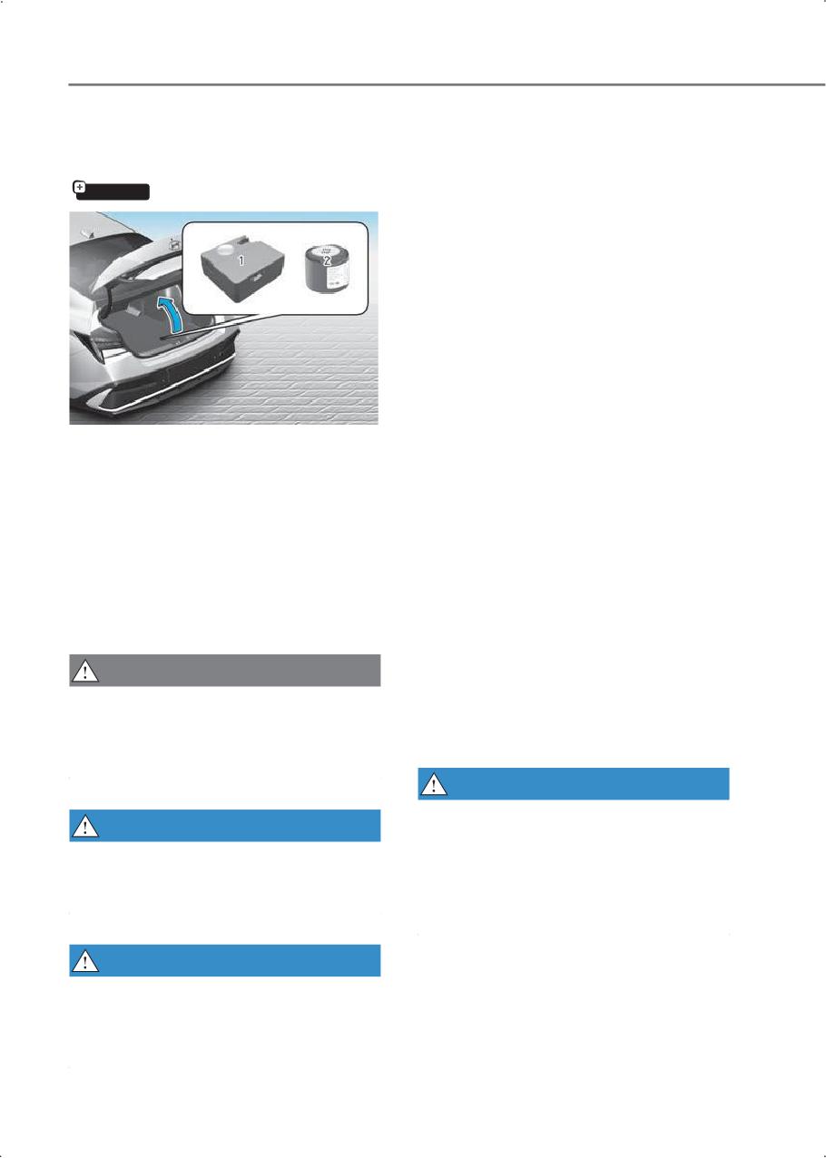
(1) Compressor
For this reason, you should avoid abrupt
(2) Sealant bottle
steering or other driving maneuvers,
The tire mobility kit is a temporary fix to
especially if the vehicle is heavily loaded
the tire. Have the tire inspected by an
or if a trailer is in use.
authorized HYUNDAI dealer or the
The Tire Mobility Kit is not designed or
equivalent approved for your vehicle as
intended as a permanent tire repair
soon as possible.
method and is to be used for one tire only.
CAUTION
This instruction shows you step by step
how to temporarily seal the puncture
When two or more tires are flat, do not
simply and reliably.
use the tire mobility kit because the
Read the section "Notes on the safe use of
sealant provided with the Tire Mobility Kit
the Tire Mobility Kit".
must be used for only one flat tire.
WARNING
Do not use the TMK if a tire is severely
WARNING
damaged by driving run flat or with
Do not use the Tire Mobility Kit to repair
insufficient air pressure.
punctures in the tire walls. This can result
Only punctured areas located within the
in an accident due to tire failure.
tread region of the tire can be sealed
using the TMK.
WARNING
Have your tire repaired as soon as
possible. The tire may lose air pressure at
any time after inflating with the Tire
Mobility Kit.
8-16
8
Notes on the safe use of the
• In case of skin contact with the sealant,
wash the area thoroughly with plenty of
Tire Mobility Kit
water. If the irritation persists, seek
•
Park your car at the side of the road so
medical attention.
that you can work with the Tire Mobility
• In case of eye contact with the sealant,
Kit away from moving traffic.
flush your eyes for at least 15 minutes. If
•
To be sure your vehicle will not move,
the irritation persists, seek medical
even when you’re on fairly level ground,
attention.
always set your parking brake.
• In case of swallowing the sealant, rinse
•
Only use the Tire Mobility Kit for
the mouth and drink plenty of water.
sealing/inflation passenger car tires.
However, never give anything to an
Only punctured areas located within
unconscious person and seek medical
the tread region of the tire can be
attention immediately.
sealed using the tire mobility kit.
• Long time exposure to the sealant may
•
Do not use on motorcycles, bicycles or
cause damage to bodily tissue such as
any other type of tires.
kidney, etc.
•
When the tire and wheel are damaged,
do not use Tire Mobility Kit for your
Components of the Tire
safety.
Mobility Kit
•
Use of the Tire Mobility Kit may not be
effective for tire damage larger than
about 0.16 in. (4 mm).
•
If the tire cannot be made roadworthy
with the Tire Mobility Kit, contact an
authorized HYUNDAI dealer.
•
Do not use the Tire Mobility Kit if a tire
is severely damaged by driving run flat
or with insufficient air pressure.
•
Do not remove any foreign objects such
as nails or screws that have penetrated
the tire.
•
Provided the car is outdoors, leave the
engine running. Otherwise operating
the compressor may eventually drain
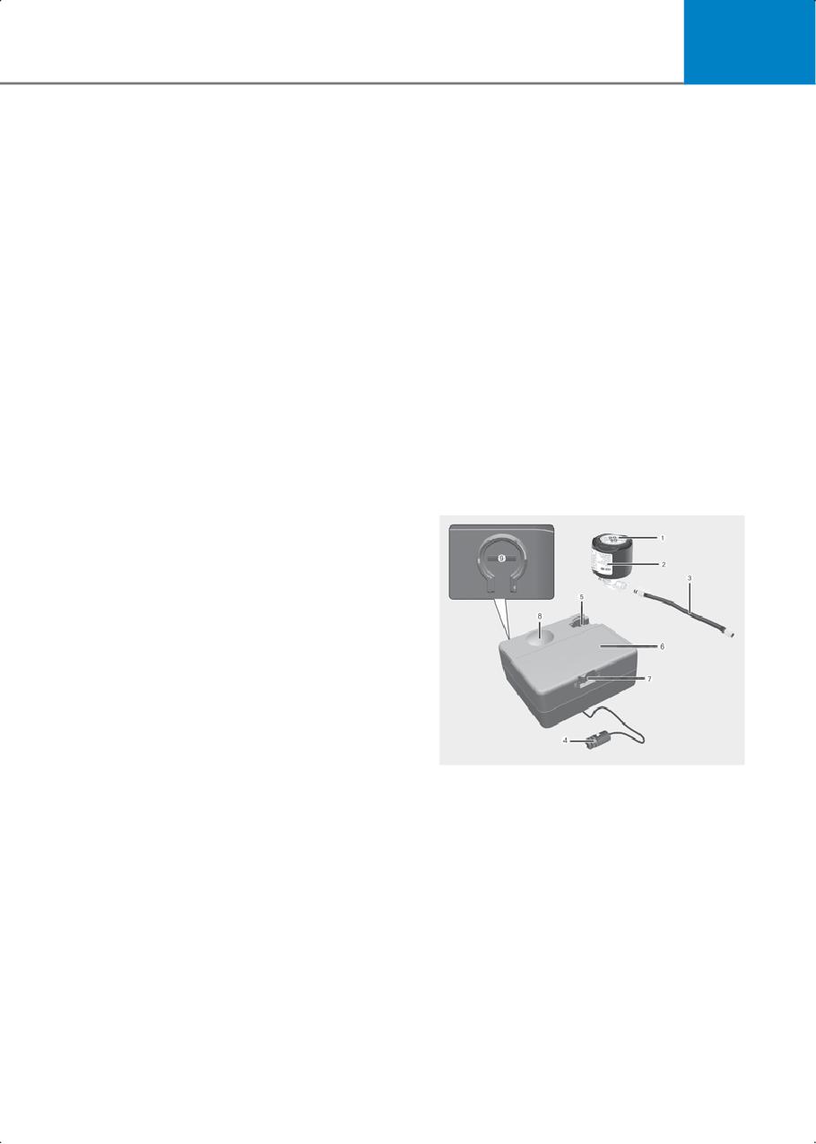
1. Speed-restriction label
the car battery.
2. Sealant bottle and label with speed
•
Never leave the Tire Mobility Kit
restriction
unattended while it is being used.
3. Filling hose
•
Do not leave the compressor running
4. Connectors and cable for the power
for more than 10 min. at a time or it may
outlet direct connection
overheat.
5. Holder for the sealant bottle
•
Do not use the Tire Mobility Kit if the
ambient temperature is below -30 °C
6. Compressor
(-22 °F).
7. ON/OFF switch
8. Pressure gauge for displaying the tire
inflation pressure
8-17
Emergency situations
9. Button for reducing the tire inflation
CAUTION
pressure
Connectors, cable and connection hose
If only the tire pressure needs to be
are stored in the compressor housing.
adjusted, refer to the "How to adjust tire
pressure" section in this chapter.
Strictly follow the specified sequence,
otherwise the sealant may escape under
Before using the Tire Mobility Kit, be fully
high pressure.
aware of the explanation on the sealant.
WARNING
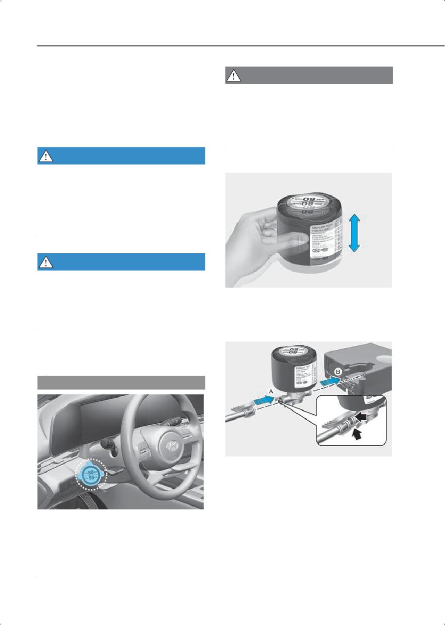
1. Shake the sealant bottle.
Expired sealant
Do not use the Tire sealant after the
sealant has expired (for example, pasted
the expiration date on the sealant
container). This can increase the risk of
tire failure.
WARNING
Sealant
• Keep out of reach of children.
• Avoid contact with eyes.
2. Connect the filling hose to the sealant
bottle in the direction of (A) and
• Do not swallow.
connect the sealant bottle to the
compressor in the direction of (B).
Using the Tire Mobility Kit
When a tire is flat
CAUTION
3. Ensure that the compressor is switched
OFF.
Detach the speed restriction label from
the sealant bottle, and place it in a highly
visible place inside the vehicle such as on
the steering wheel to remind the driver
not to drive too fast.
8-18
8
4. Unscrew the valve cap from the valve of
6. With the engine running, switch on the
the defective wheel and screw the
compressor and let it run for about 5-7
filling hose (3) of the sealant bottle onto
minutes to fill the sealant up to proper
the valve.
pressure. (refer to the "Tires and
Wheels" section in the complete
Owner'sManual). Theinflationpressure
of the tire after filling is unimportant
and will be checked/corrected later.
Be careful not to overinflate the tire and
stay away from the tire when filling it.
CAUTION
Tire pressure
Do not attempt to drive your vehicle if
the tire pressure is below 29 psi (200
kPa). This could result in an accident
due to sudden tire failure.
CAUTION
Securely install the sealant filling hose
to the valve. If not, sealant may flow
7. Switch off the compressor.
backward, possibly clogging the filling
8. Detach the hoses from the sealant
hose.
bottle connector and from the tire
valve.
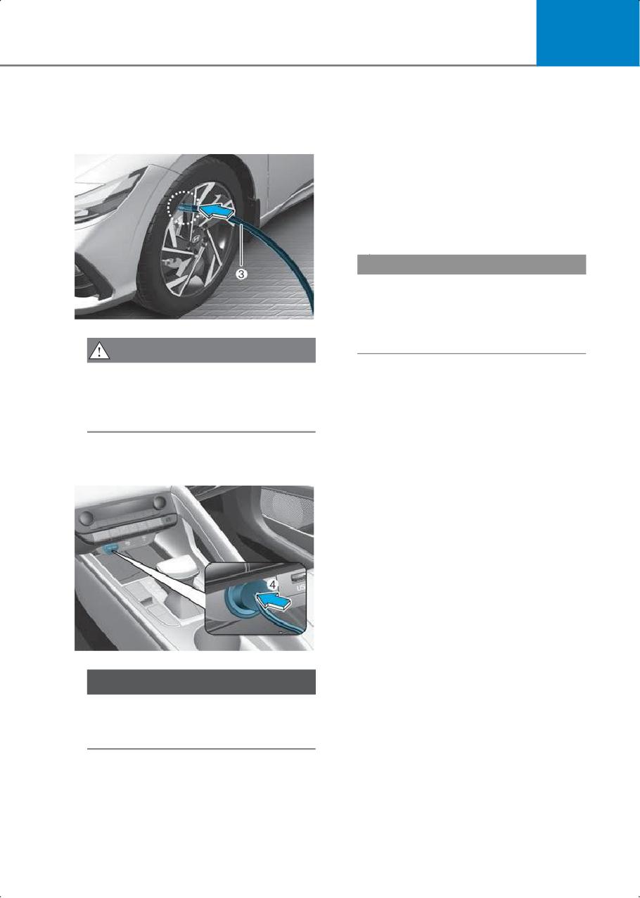
5. Plug the compressor power cord (4)
Return the Tire Mobility Kit to its
into the vehicle power outlet.
storage location in the vehicle.
NOTICE
Only use the front passenger side
power outlet when connecting the
power cord.
8-19
Emergency situations
9. Immediately drive about 4-6 mi. (7-10
13. Adjust the tire inflation pressure to the
km or, about 10 minutes) to evenly
recommended tire inflation.
distribute the sealant in the tire.
With the engine running, proceed as
follows.
• To increase the inflation pressure :
Switch on the compressor. To check
the current inflation pressure setting,
briefly switch off the compressor.
• To reduce the inflation pressure:
Press the button (9) on the
compressor.
NOTICE
Do not let the compressor run for more
than 10 minutes, otherwise the device will
overheat and may be damaged.
Do not exceed a speed of 50 mph (80
km/h). If possible, do not fall below a
speed of 12 mph (20 km/h).
While driving, if you experience any
Information
unusual vibration, ride disturbance or
The pressure gauge may show higher
noise, reduce your speed and drive with
than actual reading when the compressor
caution until you can safely pull off of
is running. To get an accurate tire reading,
the side of the road.
the compressor needs to be turned off.
Call for road side service or towing.
10.After driving about 4-6 mi. (7-10 km or
about 10 min), stop at a safety location.
CAUTION
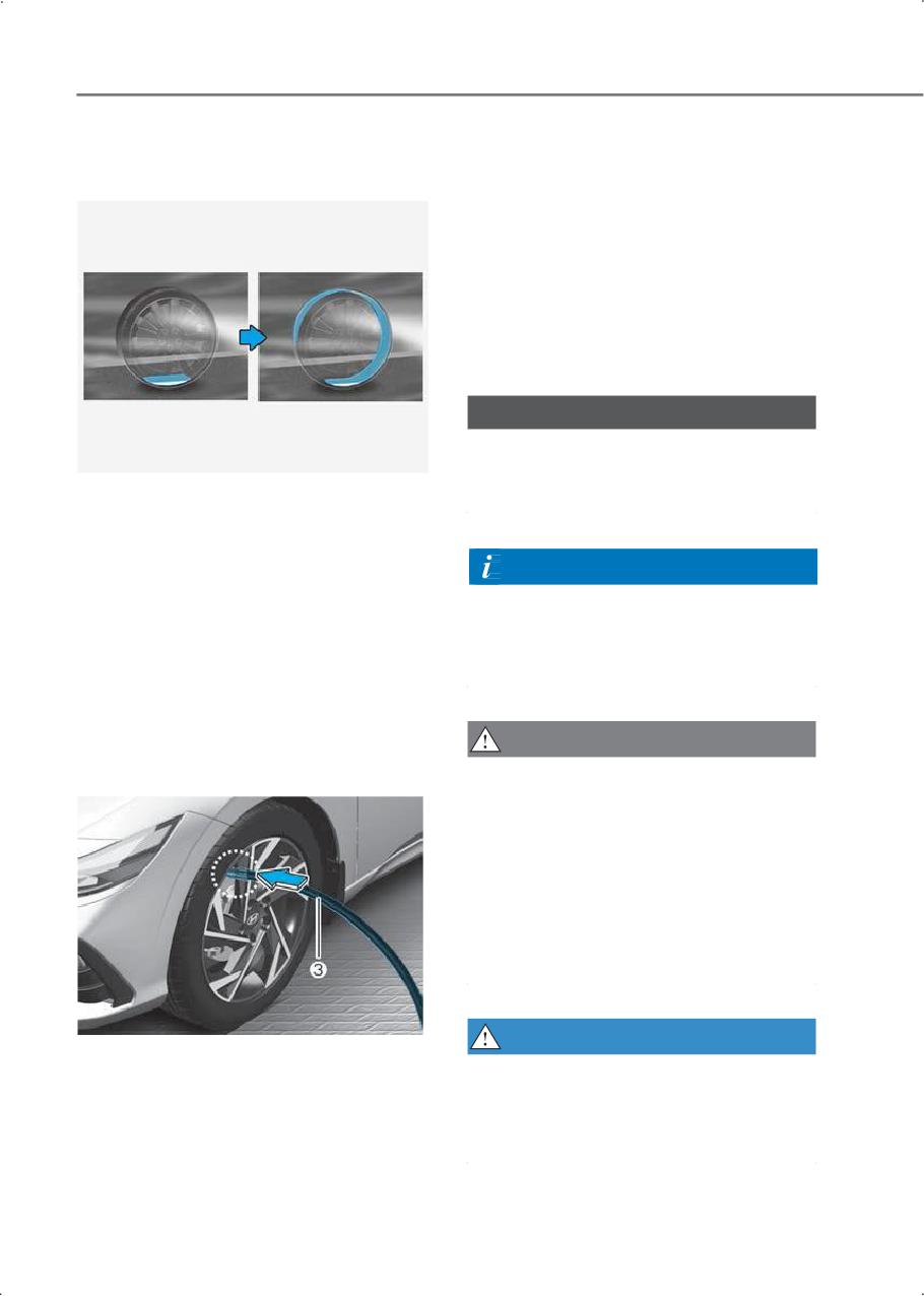
11. Connect the filling hose (3) of the
If the inflation pressure is not maintained,
compressor directly to the tire valve.
drive the vehicle a second time, refer to
step 9.
Then repeat steps 10 to 13.
Use of the TMK may be ineffectual for tire
damage larger than about 0.16 in. (4 mm).
Contact an authorized HYUNDAI dealer if
the tire cannot be made roadworthy with
the Tire Mobility Kit.
WARNING
12. Plug the compressor power cord into
The tire inflation pressure must be at least
the vehicle power outlet.
29 psi (200 kPa). If it is not, do not
continue driving.
Call for road side service or towing.
8-20
8
• To reduce the inflation pressure:
CAUTION
Press the button (9) on the
Tire pressure sensor (if equipped with
compressor.
TPMS)
NOTICE
The sealant on the tire pressure sensor
and wheel should be removed when you
Do not let the compressor run for more
replace the tire with a new one and
than 10 minutes, otherwise the device will
inspect the tire pressure sensors. Get this
overheat and may be damaged.
done at an authorized HYUNDAI dealer.
Information
Information
• The pressure gauge may show higher
When reinstalling the repaired or
than actual reading when the
replaced tire and wheel on the vehicle,
compressor is running. To get an
tighten the wheel lug nut to 79-94 lbf·ft
accurate tire reading, the compressor
(11-13 kgf·m).
needs to be turned off.
• When reinstalling the repaired or
replaced tire and wheel on the vehicle,
How to adjust tire pressure
tighten the wheel lug nut to 79-94 lbf·ft
(11-13 kgf·m).
CAUTION
Do not use the sealant when only the tire
pressure needs to be adjusted.
WARNING
The tire inflation pressure must be at least
29 psi (200 kPa). If it is not, do not
1. Park your vehicle in a safe location.
continue driving.
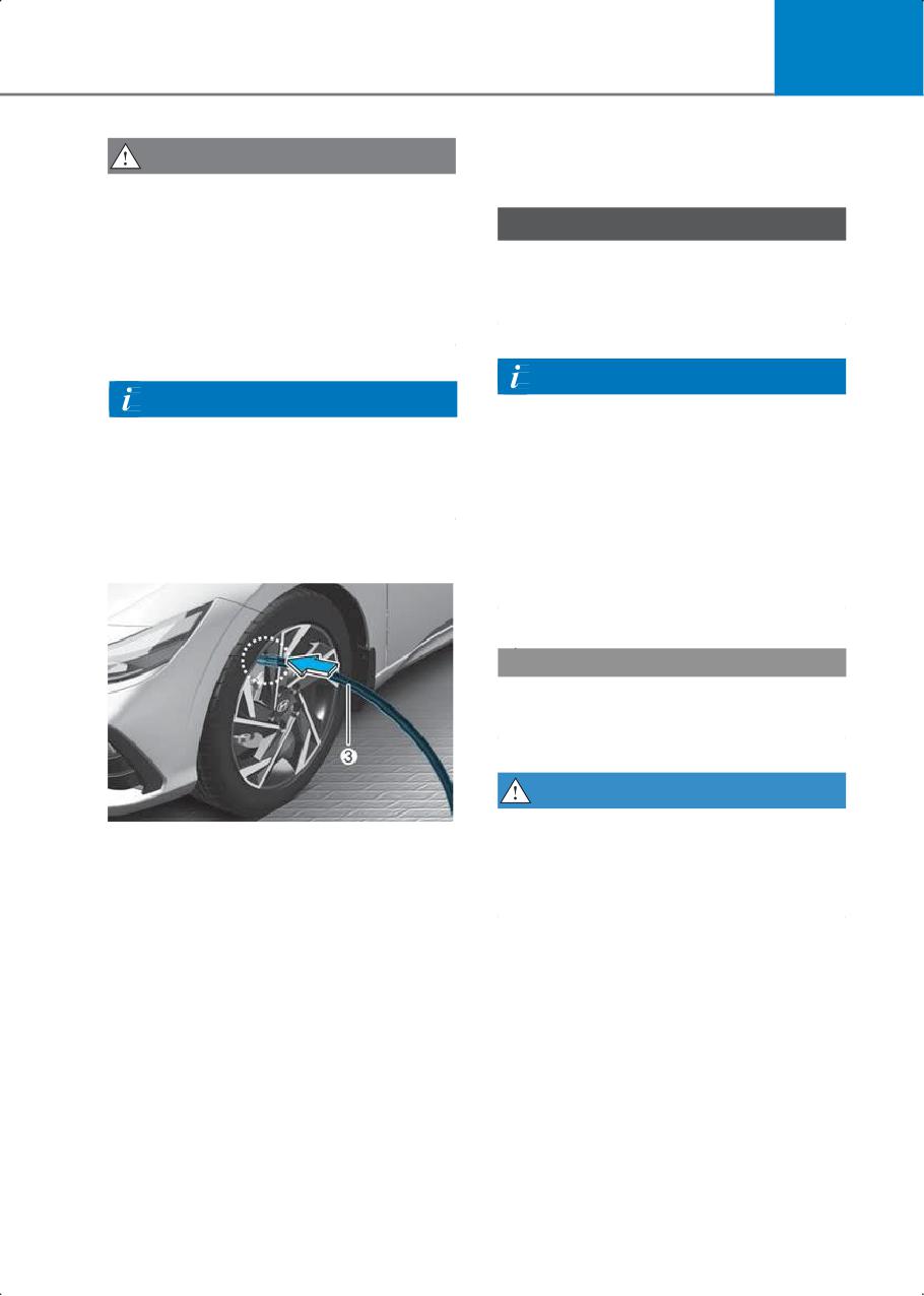
2. Connect the filling hose (3) of the
Call for road side service or towing.
compressor directly to the tire valve.
3. Plug the compressor power cord into
the vehicle power outlet.
4. Adjust the tire inflation pressure to the
recommended tire inflation.
With the engine running, proceed as
follows.
• To increase the inflation pressure:
Switch on the compressor. To check
the current inflation pressure setting,
briefly switch off the compressor.
8-21
9. Maintenance
Engine Compartment
Engine oil
Checking the engine oil level
Checking the engine oil and filter
Engine coolant
Checking the coolant level
Changing coolant
Brake fluid
Checking the brake fluid level
Parking brake
Checking the parking brake
Washer fluid
Checking the washer fluid level
Air cleaner
Filter replacement
Wiper blades
Blade inspection
Blade replacement
Battery
For longer battery life
Battery capacity label
Battery recharging
Reset items
Tires and wheels
Tire care
Recommended cold tire inflation pressures
9
Check tire inflation pressure
Tire rotation
Wheel alignment and tire balance
Tire replacement
Wheel replacement
Tire traction
Tire maintenance
Tire sidewall labeling
Tire terminology and definitions
California perchlorate notice
Maintenance
Engine Compartment
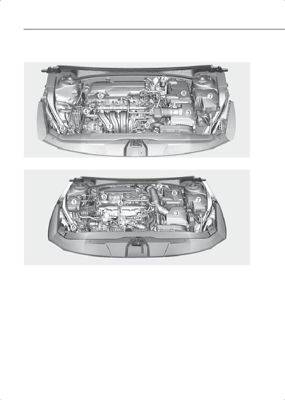
Smartstream G2.0
Smartstream G1.6 T-GDI
The actual engine compartment in the vehicle may differ from the illustration.
(1) Engine coolant reservoir
(2) Brake fluid reservoir
(3) Air cleaner
(4) Engine oil dipstick
(5) Engine oil filler cap
(6) Windshield washer fluid reservoir
(7) Fuse box
(8) Battery
(9) Radiator cap
9-2
9
Smartstream G1.6 T-GDI
Engine oil
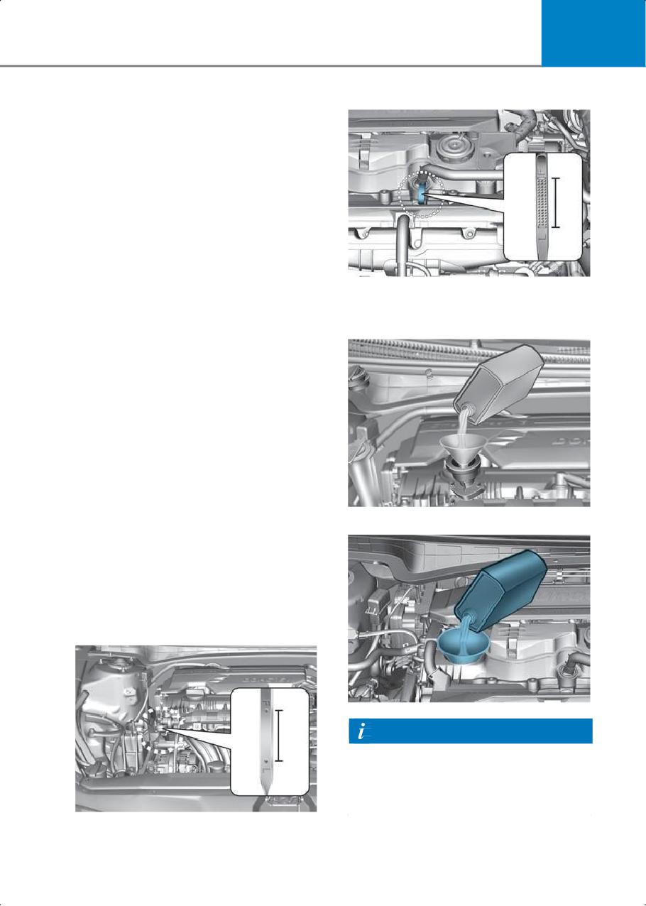
Checking the engine oil level
Engine oil is used for lubricating, cooling,
and operating various hydraulic
components in the engine. Engine oil
consumption while driving is normal, and
it is necessary to check and refill the
engine oil regularly. Also, check and refill
the oil level within the recommended
maintenance schedule to prevent
deterioration of oil performance.
7. If the oil level is below the L, add
Check the engine oil following the below
enough oil to bring the level to F.
procedure.
Smartstream G2.0
1. Follow all of the oil manufacturer’s
precautions.
2. Make sure the vehicle is on the level
ground in P (Park) with the parking
brake set and the wheels blocked.
3. Turn the engine on and warm the
engine up until the coolant
temperature reaches a constant normal
temperature.
4. Turn the engine off, and remove the oil
filler cap and pull the dipstick out. Wait
for 15 minutes for the oil to return to the
Smartstream G1.6 T-GDI
oil pan.
5. Wipe the dipstick clean and re-insert it
fully.
6. Pull the dipstick out again and check
the level. The level should be between F
(Full) and L (Low).
Smartstream G2.0
Information
Use only the specified engine oil (Refer to
the "Recommended lubricants and
capacities" in the complete Owner's
Manual).
9-3
Maintenance
• The purpose of the maintenance
NOTICE
schedule for engine oil replacement is
To prevent damage to your engine:
to prevent oil deterioration and it is
irrelevant to oil consumption. Check
• Do not spill engine oil when adding or
and refill engine oil regularly.
changing engine oil. Wipe off spilled oil
immediately.
Information
• The engine oil consumption may
When the oil pressure is low due to
increase while you break in the new
insufficient engine oil, the Engine Oil
vehicle, and it should stabilize after
driving 4,000 mi. (6,000 km).
Pressure (
) warning light will
illuminate.
• The engine oil consumption may be
affected by driving habits, climate
In addition, the enhanced engine
conditions, traffic conditions, and oil
protection system, which limits the
quality. Inspect the engine oil level
engine’s power is activated and the
regularly and refill if necessary.
Malfunction Indicator Lamp (
) will
illuminate when the vehicle is driven in
this state continuously. When the engine
Checking the engine oil and
oil pressure is restored, the warning light
filter
and the enhanced engine protection
system will turn off after the engine is
restarted. (Smartstream G1.6 T-GDi)
WARNING
Allow the engine to cool before replacing
the oil.
NOTICE
• The lubrication, rust prevention,
Never add any additives to the engine oil.
cooling, and cleaning effect of the
Engine oil additives can change the
engine oil will gradually degrade during
properties of engine oil and may cause
its use. Have the engine oil and filter
serious engine failure.
changed by an authorized HYUNDAI
dealer according to the Oil Life
Management System instructions or
the Maintenance Schedule in the
complete Owner's Manual.
• To keep the engine in optimal
condition, use the recommended
engine oil and filter. If the
recommended engine oil and filter are
not used, replace them according to
the Maintenance Schedule Under
Severe Usage Conditions.
9-4
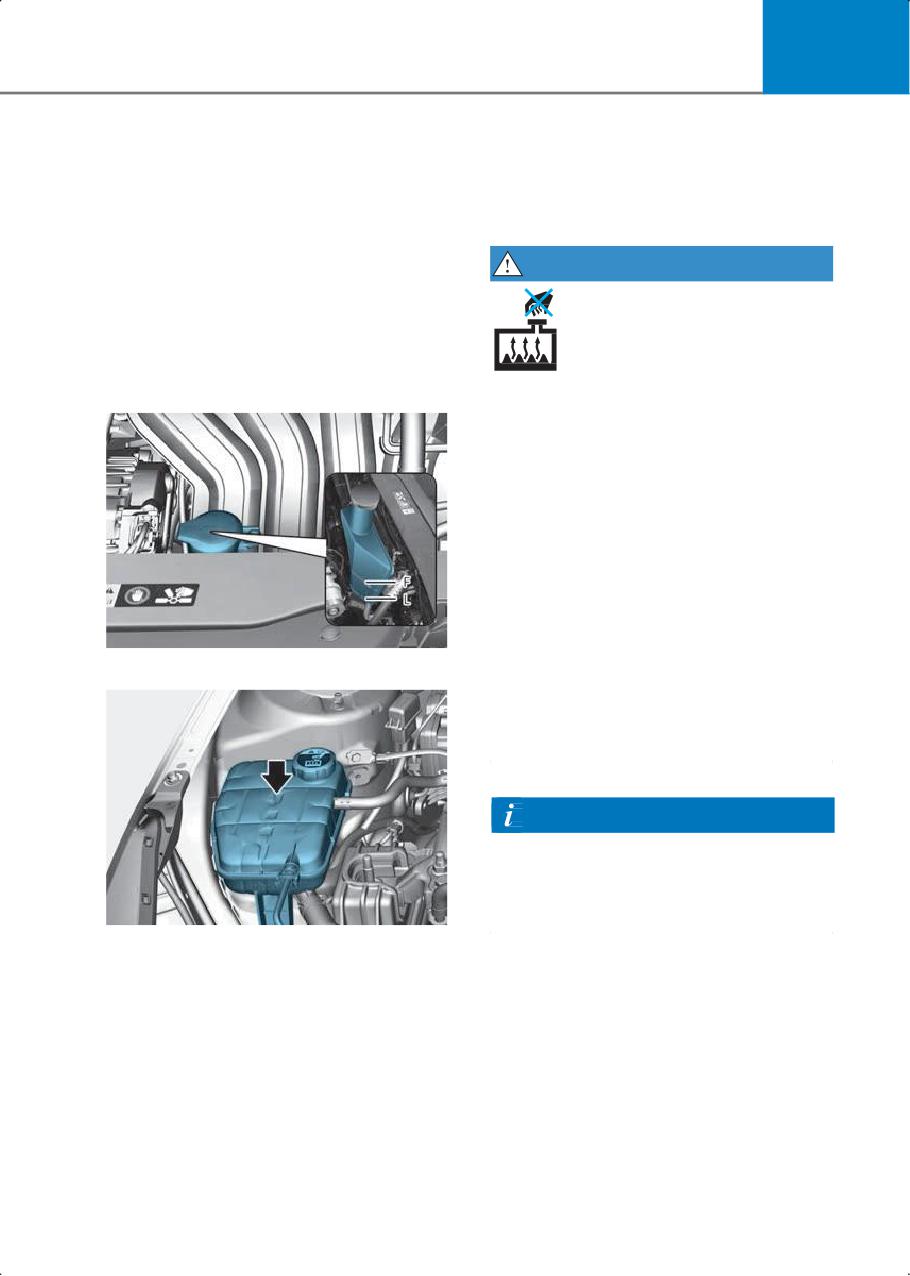
9
If the coolant level is low, add enough
Engine coolant
distilled (deionized) water mixed with
The high pressure cooling system has a
antifreeze to bring the level to the MAX
reservoir filled with year-round antifreeze
mark. If frequent additions are required,
coolant.
contact an authorized HYUNDAI dealer.
Check the antifreeze protection and
WARNING
coolant level at least once a year, before
the winter season or before traveling to a
colder climate.
Checking the coolant level
Smartstream G2.0
Never remove the engine coolant
reservoir cap, radiator cap, or drain plug
while the engine and radiator are hot. Hot
coolant and steam may blow out under
pressure, causing serious injury.
Turn the vehicle off and wait until the
engine cools down. Use extreme care
when removing the engine coolant
reservoir cap and radiator cap. Wrap a
thick towel around it, and turn it
counterclockwise slowly to the first stop.
Step back while the pressure is released
from the cooling system. When you are
Smartstream G1.6 T-GDI
sure all the pressure has been released,
press down on the cap using a thick
towel, and continue turning
counterclockwise to remove it.
Information
The coolant level is influenced by the
engine temperature. Before checking or
refilling the coolant, turn off the engine
and allow the engine to cool.
Check the condition and connections of
all cooling system hoses and heater
hoses. Replace any swollen or
deteriorated hoses.
The coolant level should be filled between
the MAX and the MIN marks on the side of
the coolant reservoir when the engine is
cool.
9-5
Maintenance
WARNING
Keep hands, clothing, and tools away
from the rotating fan blades of the
cooling fan.
Always turn off the vehicle unless the
vehicle has to be inspected with the
engine on. The cooling fan may operate
Recommended coolant
automatically if the negative (-) battery
terminal is not disconnected.
• When adding coolant, use only
deionized water, distilled water, or soft
water for your vehicle and never mix
hard water in the coolant filled at the
WARNING
factory.
Make sure the coolant cap is properly
• An incorrect coolant mixture may result
closed after refilling coolant. Otherwise,
in severe malfunction or engine
the engine may be overheated while
damage.
driving.
• The engine in your vehicle has
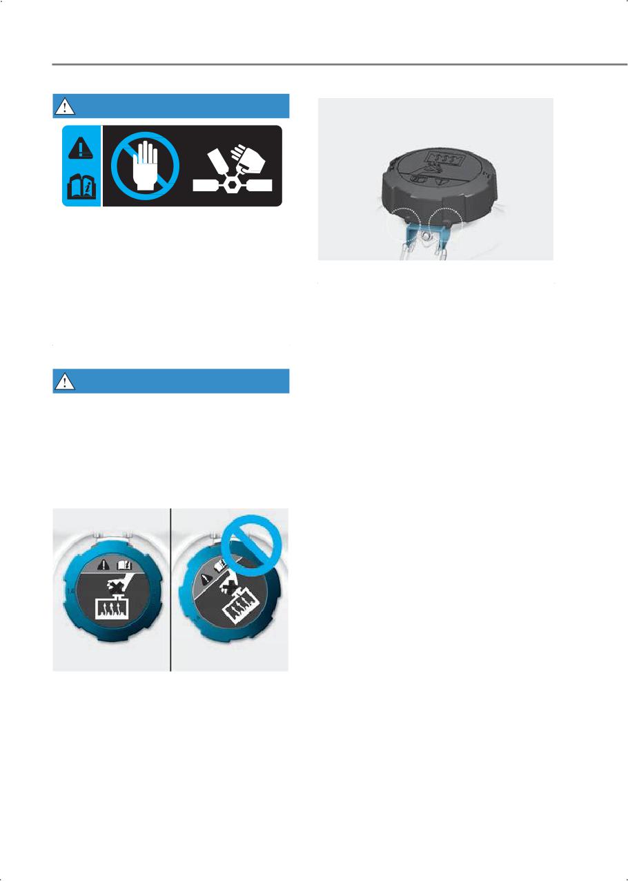
1. Check if the coolant cap label is straight
aluminum engine parts and must be
in front.
protected by an phosphate-based
Engine compartment front view
ethylene glycol coolant to prevent
corrosion and freezing.
• Do not use alcohol or methanol coolant
or mix them with the specified coolant.
• Do not use a solution that contains
more than 60 % antifreeze or less than
35 % antifreeze, which could reduce the
effectiveness of the solution.
2. Make sure that the tiny protrusions
inside the coolant cap is securely
interlocked.
9-6
9
For mixing percentage, refer to the
Brake fluid
following table:
Mixture Percentage
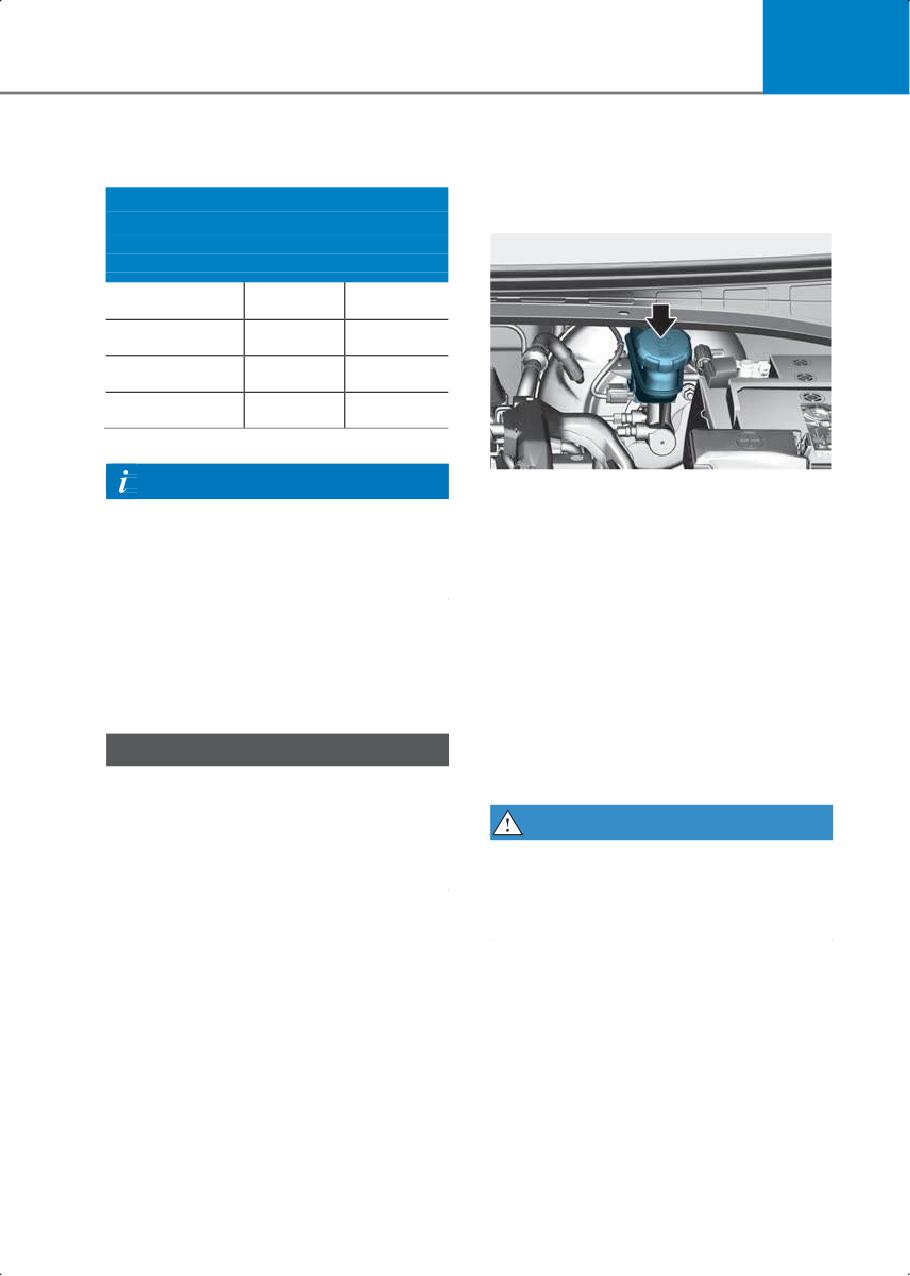
Checking the brake fluid level
Ambient
(volume)
Temperature
Antifreeze
Water
5 °F (-15 °C)
35
65
-13 °F (-25 °C)
40
60
-31 °F (-35 °C)
50
50
-49 °F (-45 °C)
60
40
Information
Check the fluid level in the reservoir
If in doubt about the mix ratio, a 50 %
periodically. The fluid level must be
water and 50 % antifreeze mix is the
between the MAX and the MIN marks on
easiest to mix together because it is the
the side of the reservoir.
same quantity for each.
Before removing the reservoir cap and
adding brake fluid, clean the area around
the reservoir cap thoroughly to prevent
Changing coolant
brake fluid contamination.
Have the coolant changed by an
If the level is low, add the specified brake
authorized HYUNDAI dealer according to
fluid to the MAX level. If the fluid level is
the Maintenance Schedule.
excessively low or frequent additions are
required, have the brake system
NOTICE
inspected by an authorized HYUNDAI
To prevent damage to engine parts, put a
dealer.
thick towel around the engine coolant
cap before refilling the coolant to prevent
WARNING
the coolant from overflowing into engine
If brake fluid comes in contact with your
parts, such as the alternator.
eyes, flush your eyes with clean water for
at least 15 minutes and get immediate
medical attention.
9-7
Maintenance
NOTICE
Parking brake
• Do not allow brake fluid to contact the
vehicle’s body paint, because paint
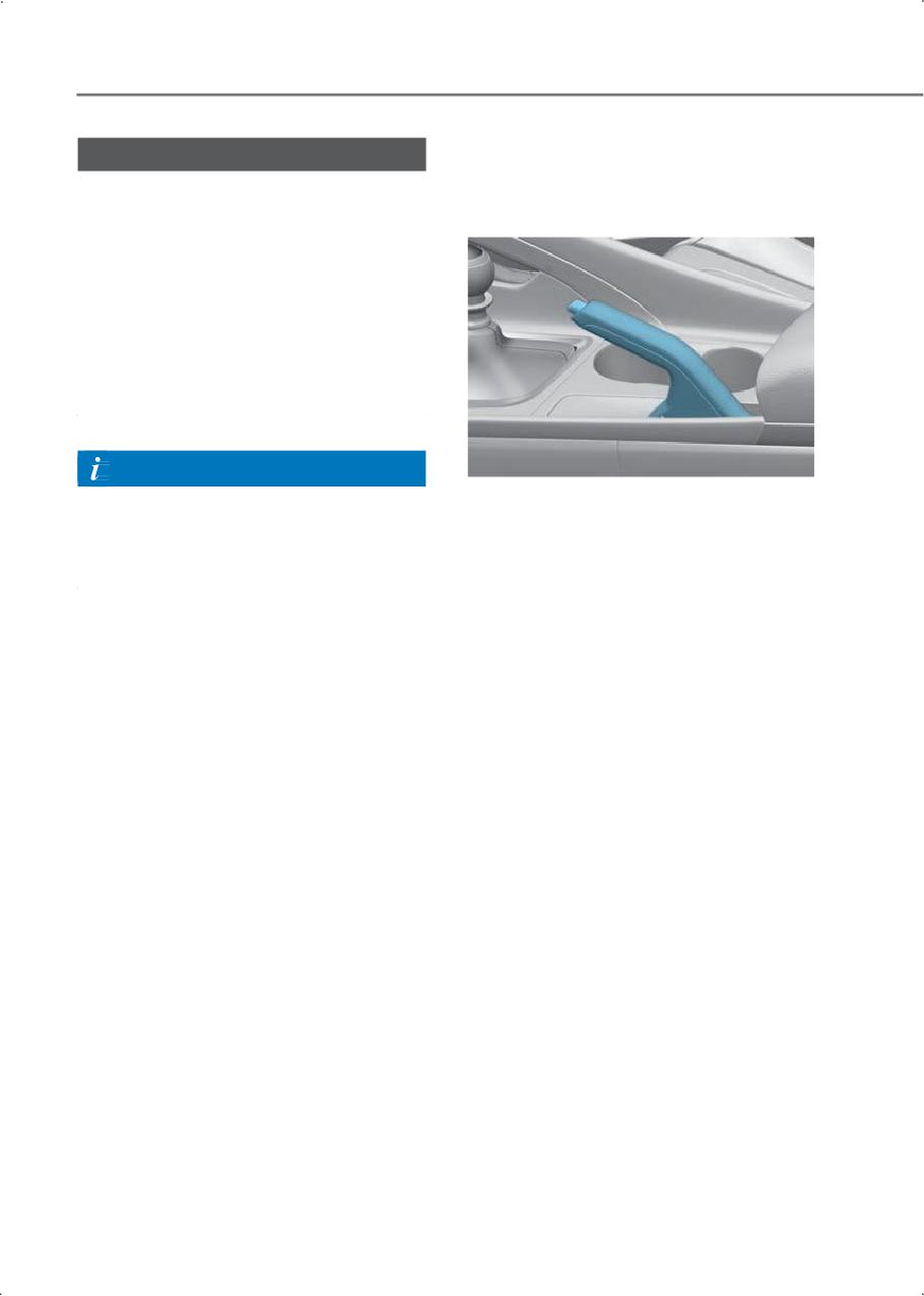
Checking the parking brake
damage may occur.
• Never use brake fluid that has been
exposed to open air for an extended
time and dispose of it properly.
• Do not use the wrong type of brake
fluid. A few drops of mineral based oil
such as engine oil in your brake system
may damage the brake system parts.
Information
Use only the brake fluid specified in the
Check the stroke of the parking brake by
"Recommended lubricants and
counting the number of "clicks’’ heard
capacities" in the complete Owner's
while fully applying it from the released
Manual.
position. Also, the parking brake alone
should securely hold the vehicle on a
fairly steep grade. If the stroke is more or
less than specified, have the system be
inspected by an authorized HYUNDAI
dealer.
Stroke : 5-8 "clicks’’ at a force of 44 lbs
(20 kg, 196 N)
9-8
9
Washer fluid
Air cleaner
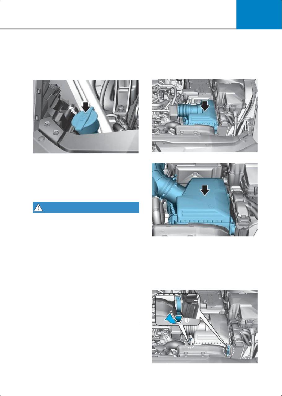
Checking the washer fluid
Filter replacement
level
Type A
Type B (N Line)
Check the fluid level in the washer fluid
reservoir and add fluid if necessary. Plain
water can be used during summer
months if washer fluid is not available.
However, use washer fluid with antifreeze
in cold climates to prevent freezing.
WARNING
To prevent serious injury or death:
• Do not use engine coolant or antifreeze
in the washer fluid reservoir. Engine
coolant can severely limit your visibility
The air cleaner filter can be cleaned for
when sprayed on the windshield and
inspection using compressed air. Do not
may cause loss of vehicle control
attempt to wash or rinse it, because water
resulting in a collision.
can damage the filter. If soiled, replace
• Do not allow sparks or flame to contact
the air cleaner filter.
the washer fluid or the washer fluid
1. Loosen the air cleaner cover attaching
reservoir. Washer fluid may contain
clip (1) and open the cover.
alcohol and can be flammable.
• Do not drink washer fluid and avoid
contact with skin.
• Keep washer fluid away from children
and animals.
9-9
Maintenance
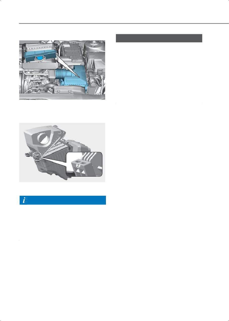
2. Replace the air cleaner filter.
NOTICE
• Do not drive with the air cleaner filter
removed. This may result in excessive
engine wear.
• When removing the air cleaner filter, be
careful that dust or dirt does not enter
the air intake. It may cause damage.
• Use HYUNDAI genuine parts or the
equivalent specified for your vehicle.
Use of non-genuine parts may damage
the air flow sensor.
3. Insert the air cleaner cover in the hinge
(2) and engage the clip (1) after closing
the cover.
4. Check that the cover is firmly installed.
Information
If the vehicle is operated in extremely
dusty or sandy areas, replace the element
more often than the usual recommended
intervals (refer to the "Maintenance under
severe usage conditions" in the complete
Owner's Manual).
9-10
9
Front windshield wiper blade
Wiper blades
replacement
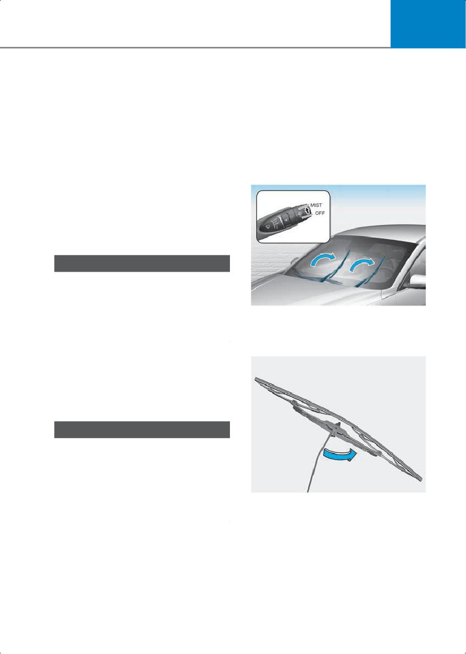
This vehicle has a "hidden" wiper design
Blade inspection
that cannot be lifted when in their bottom
resting position.
Contamination of the windshield or wiper
1. Within 20 seconds of turning off the
blades with foreign substances may
reduce the effectiveness of the
engine, lift and hold the wiper lever up
windshield wipers.
to the MIST position for about 2
seconds until the wipers move to the
Common sources of contamination are
top wipe position.
insects, tree sap, and hot wax treatments
used by some commercial car washes. If
the blades are not wiping properly, clean
both the window and the blades with
glass cleaner or mild detergent, and rinse
thoroughly with clean water. Replace
blades as needed.
NOTICE
To prevent damage to the wiper blades,
arms, or other components, do not:
• Use gasoline, kerosene, paint thinner,
or other solvents on or near them.
2. Lift the wipers off the windshield.
• Attempt to move the wipers manually.
3. Rotate the wiper blade to access the
clip.
Blade replacement
When the wipers no longer clean
adequately, the blades may be worn or
cracked. Replace the wipers with new
ones.
NOTICE
To prevent damage:
• Never use non-specified wiper blades.
• Lift the wiper arms when in the top
wiping position.
• Always return the wiper arms to the
windshield before driving.
9-11
Maintenance
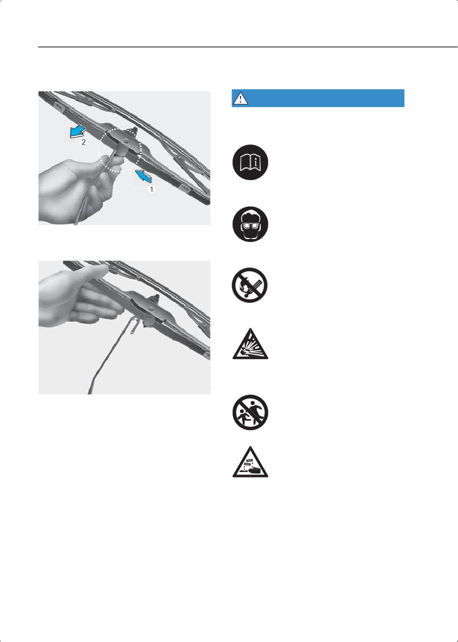
4. While pushing the clip (1), pull down the
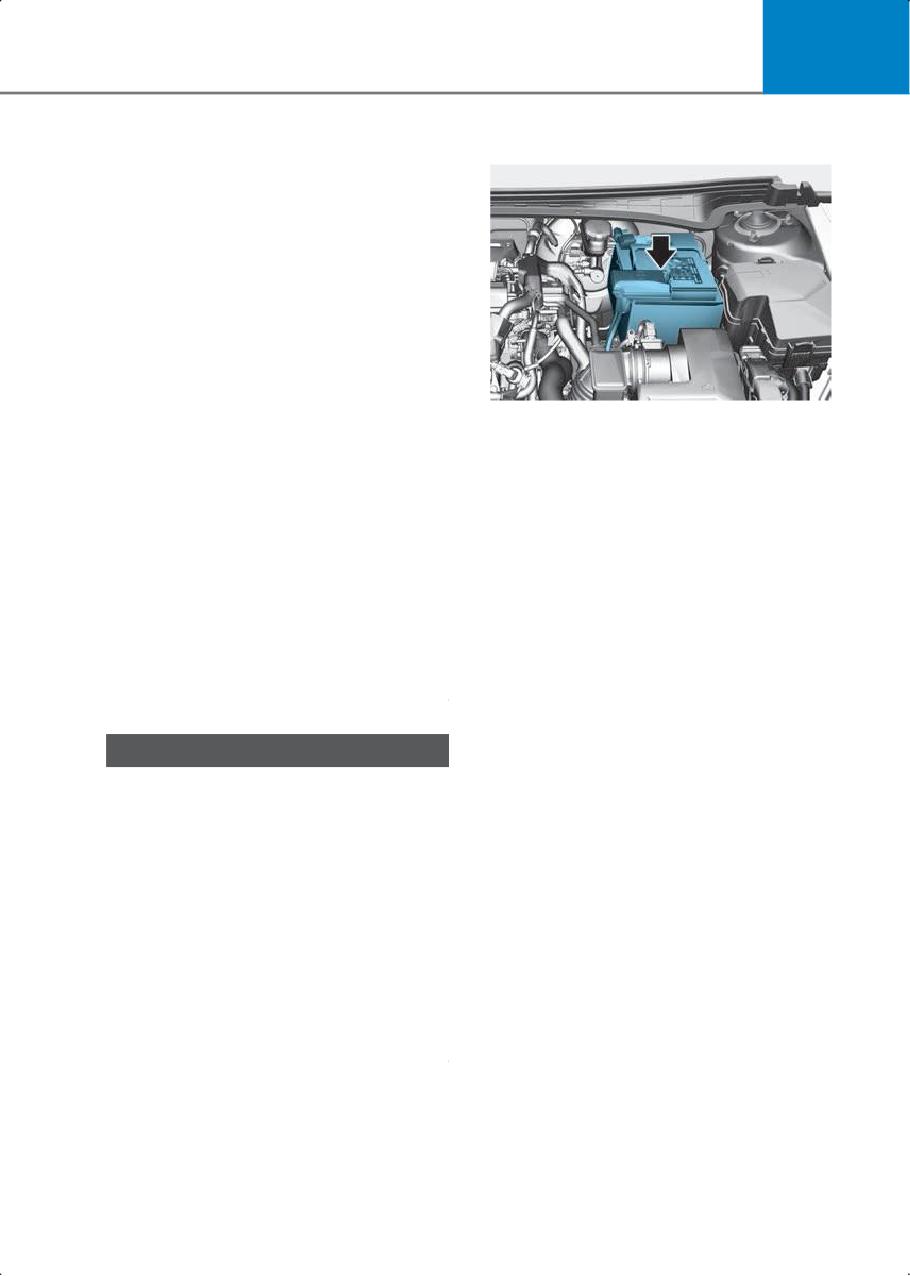
Battery
wiper blade (2).
WARNING
To prevent serious injury or death to you
or bystanders when working near or
handling the battery:
Always read and follow instructions
carefully when handling a battery.
5. Remove the wiper blade from the wiper
arm.
Wear eye protection designed to protect
the eyes from acid splashes.
Keep all flames, sparks, or smoking
materials away from the battery.
Hydrogen is always present in battery
cells, is highly combustible, and may
explode if ignited.
6. Install a new wiper blade assembly in
the reverse order of removal.
7. Gently put down the wiper back onto
Keep batteries out of reach of children.
the windshield.
8. Turn the wipers to any ON position to
return the wiper arms to the bottom
resting position.
Batteries contain sulfuric acid that is
highly corrosive. Do not allow acid to
contact your eyes, skin, or clothing.
If acid gets into your eyes, flush your eyes
with clean water for at least 15 minutes
and get immediate medical attention. If
acid gets on your skin, thoroughly wash
the area. If you feel pain or a burning
sensation, get medical attention
immediately.
9-12
9
•
Lift a battery with a battery carrier or
For longer battery life
with your hands on opposite corners.
When lifting a plastic-cased battery,
excessive pressure on the case may
cause battery acid to leak.
•
Do not attempt to jump start your
vehicle if your battery is frozen.
•
Never attempt to recharge the battery
when the vehicle’s battery cables are
connected to the battery.
•
The electrical ignition system works
with high voltage. Never touch these
components with the engine running or
when the ignition switch is in the ON
•
Keep the battery top clean and dry.
position.
•
Keep the terminals and connections
•
Do not allow the (+) and (-) jumper
clean, tight, and coated with petroleum
cables to touch. It may cause sparks.
jelly or terminal grease.
•
The battery may rupture or explode
•
Rinse any spilled electrolyte from the
when you jump start with a low or
battery immediately with a solution of
frozen battery.
water and baking soda.
•
Leaked battery electrolyte due to
•
If the vehicle is not going to be used for
repeated driving on sharp curves (for
an extended period of time, disconnect
example, on circuits) may cause safety
the battery cables.
problem. Avoid repeated driving on
sharp curves.
NOTICE
To prevent battery damage:
• Always fully charge the battery and
store indoors when you do not plan to
use the vehicle for a long time if the
outside temperature is low enough to
cause the battery to freeze.
• Never connect unauthorized devices to
the battery.
• Always fully charge the battery to
prevent battery case damage in low
temperature areas.
• Do not tilt the battery.
9-13
Maintenance
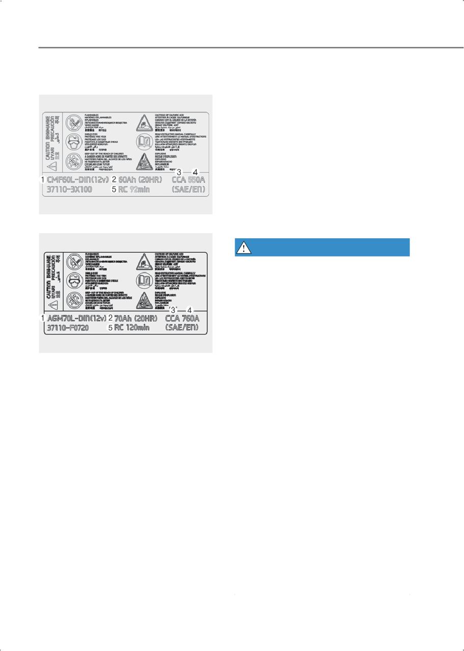
Battery capacity label
Battery recharging
Type A
By battery charger
Your vehicle has a maintenance-free,
calcium-based battery.
• If the battery becomes discharged over
a short time (because, for example, the
headlights or interior lights are left on
while the vehicle is not used), recharge
it by slow charging (trickle) for 10 hours.
• If the battery gradually discharges
because of high electrical load while
the vehicle is being used, recharge at
Type B
20-30 A for two hours.
WARNING
To prevent the risk of serious injury or
death from explosions or acid burns:
•
Before performing maintenance or
recharging the battery, turn off all
accessories and stop the engine.
•
Keep all flames, sparks, or smoking
materials away from the battery.
•
Always work outdoors or in an area with
plenty of ventilation.
1.
• CMF60L-DIN/AGM70L-DIN: The
HYUNDAI model name of battery
•
Wear eye protection when checking the
battery during charging. Do not contact
• 12V: The nominal voltage
the battery. This may result in serious
2. 60Ah (20HR)/70Ah (20HR): The
injury.
nominal capacity (in Ampere hours)
•
Remove the battery from the vehicle
3. CCA: The cold-test current in amperes
and place it in a well ventilated area.
by SAE
•
Watch the battery during charging, and
4. 550A/760A: The cold-test current in
stop or reduce the charging rate if the
amperes by EN
battery cells begin boiling violently.
5. RC 92min/RC 120min: The nominal
•
Remove the negative battery cable first
capacity (in Ampere hours)
and install it last when the battery is
disconnected. Disconnect the battery
charger in the following order:
1. Turn off the battery charger main
switch.
2. Unhook the negative clamp from the
negative battery terminal.
3. Unhook the positive clamp from the
positive battery terminal.
9-14

9
Reset items
NOTICE
The following items may need to be reset
AGM battery (if equipped)
after the battery has been discharged or
Absorbent Glass Mat (AGM) batteries are
disconnected:
maintenance-free and should be serviced
• Auto up/down window (refer to chapter
by an authorized HYUNDAI dealer. Only
5)
charge using fully automatic battery
• Sunroof (refer to chapter 5)
chargers that are specifically for AGM
batteries.
• Trip computer (refer to section in the
complete Owner's Manual)
• Climate control additional features
(refer to chapter 5)
CAUTION
• Do not open or remove the cap on top
of the battery. This may cause leaks of
internal electrolyte that could result in
severe injury.
• Do not charge the AGM battery with a
general charger. It may damage or
explode the AGM battery. Only charge
the AGM battery with a charger that has
AGM battery setting.
By jump starting
After a jump start from a good battery,
drive the vehicle for 30 minutes or
operate at idle for at least 60 minutes
before it is shut off. The vehicle may not
restart if you shut it off before the battery
had a chance to adequately recharge.
Refer to the "Jump starting" section in
chapter 8 for more information on jump
starting procedures.
Information
An inappropriately disposed battery may
be harmful to the environment and
human health. Always dispose of a used
battery according to your local law(s) or
regulations.
9-15
Maintenance
Tires and wheels
Tire care
For proper maintenance, safety, and
WARNING
maximum fuel economy, always
maintain the recommended tire
Tire failure may cause loss of vehicle
inflation pressures and stay within
control and result in a collision. To
the load limits and weight
reduce risk of serious injury or death:
distribution recommended for your
•
Inspect your tires monthly for
vehicle.
proper inflation as well as wear and
damage.
•
The recommended cold tire
pressure for your vehicle can be
found in this manual and on the tire
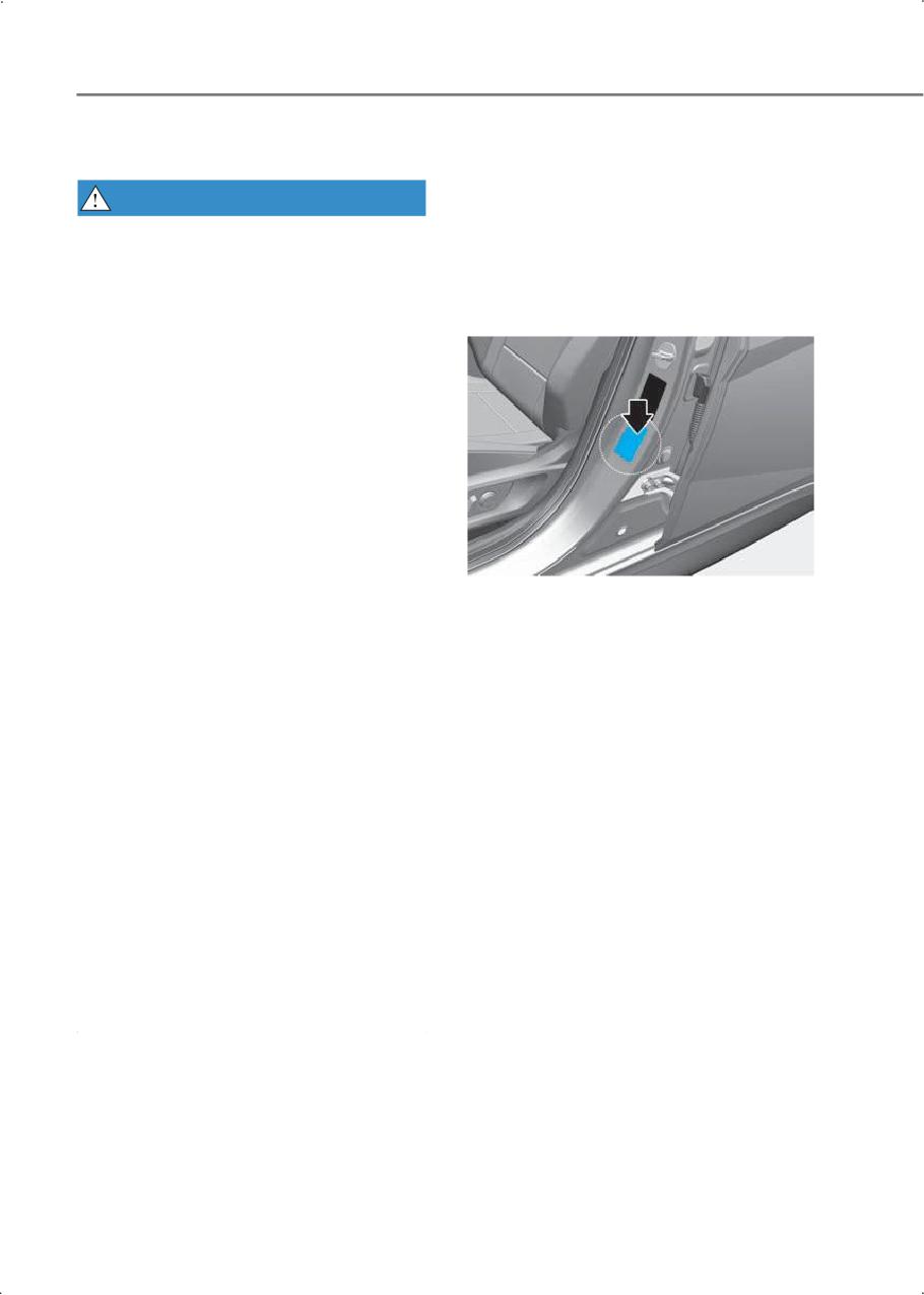
label located on the driver’s side
center pillar. Always use a tire
pressure gauge to measure tire
pressure. Tires with too much or
too little pressure wear unevenly
causing poor handling.
•
Check the pressure of the spare
All specifications (sizes and
every time you check the pressure
pressures) can be found on a label
of the other tires on your vehicle.
attached to the driver’s side center
•
Replace tires that are worn, show
pillar.
uneven wear, or are damaged.
Worn tires may cause loss of
Recommended cold tire
braking effectiveness, steering
inflation pressures
control, or traction.
Check all tire pressures (including the
•
Always replace tires with the same
spare) when the tires are cold. "Cold
size, type, construction, and tread
tires" mean the vehicle has not been
pattern as each tire that was
driven for at least three hours or
originally supplied with this vehicle.
driven less than 1 mi. (1.6 km).
Using tires and wheels other than
the recommended sizes may cause
Warm tires normally exceed the
unusual handling characteristics,
recommended cold tire pressures by
poor vehicle control, or negatively
4 to 6 psi (28 to 41 kPa). Do not
affect your vehicle’s Anti-Lock
release air from warm tires to adjust
Brake System (ABS).
the pressure. The tires are
under-inflated. For the
recommended inflation pressure,
refer to the "Tires and Wheels"
section in the complete Owner's
Manual.
9-16
9
Check tire inflation pressure
WARNING
Check your tires, including the spare
• Recommended pressures must be
tire, at least once a month.
maintained for the best ride,
vehicle handling, and minimum tire
How to check
wear.
Use a good quality tire pressure
• Over-inflation or under-inflation
gauge to check the tire pressure. You
can reduce tire life, adversely affect
cannot tell if your tires are properly
vehicle handling, and lead to
inflated simply by looking at them.
sudden tire failure that may result
Radial tires may look properly inflated
in loss of vehicle control resulting in
when they are under- inflated.
a collision.
Remove the valve cap from the tire
• Severe under-inflation may lead to
valve stem. Press the tire gauge
severe heat build-up, causing
firmly onto the valve to get a pressure
blowouts, tread separation, and
measurement. If the cold tire inflation
other tire failures that result in loss
pressure matches the recommended
of vehicle control resulting in a
pressure on the tire and loading
collision. This risk is much higher on
information label, no further
hot days and when driving for a
adjustment is necessary. If the
long time at high speeds.
pressure is low, add air until it
• Under-inflation may cause
reaches the recommended pressure.
excessive wear, poor handling, and
Be sure to put the valve caps back on
reduced fuel economy. Wheel
the valve stems. Without the valve
deformation is also possible. Keep
cap, dirt or moisture may get into the
your tire pressures at the proper
valve core and cause air leakage. If a
levels. If a tire frequently needs
valve cap is missing, install a new one
refilling, have it inspected by an
as soon as possible.
authorized HYUNDAI dealer.
If you overfill the tire, release air by
• Over-inflation produces a harsh
pushing on the metal stem in the
ride, excessive wear at the center of
center of the tire valve. Recheck the
the tire tread, and a greater
tire pressure with the tire gauge. Be
possibility of damage from road
sure to put the valve caps back on the
hazards.
valve stems. Without the valve cap,
dirt or moisture may get into the
valve core and cause air leakage. If a
valve cap is missing, install a new one
as soon as possible.
9-17
Maintenance
Tire rotation
WARNING
To equalize tread wear, HYUNDAI
• Do not use the compact spare tire
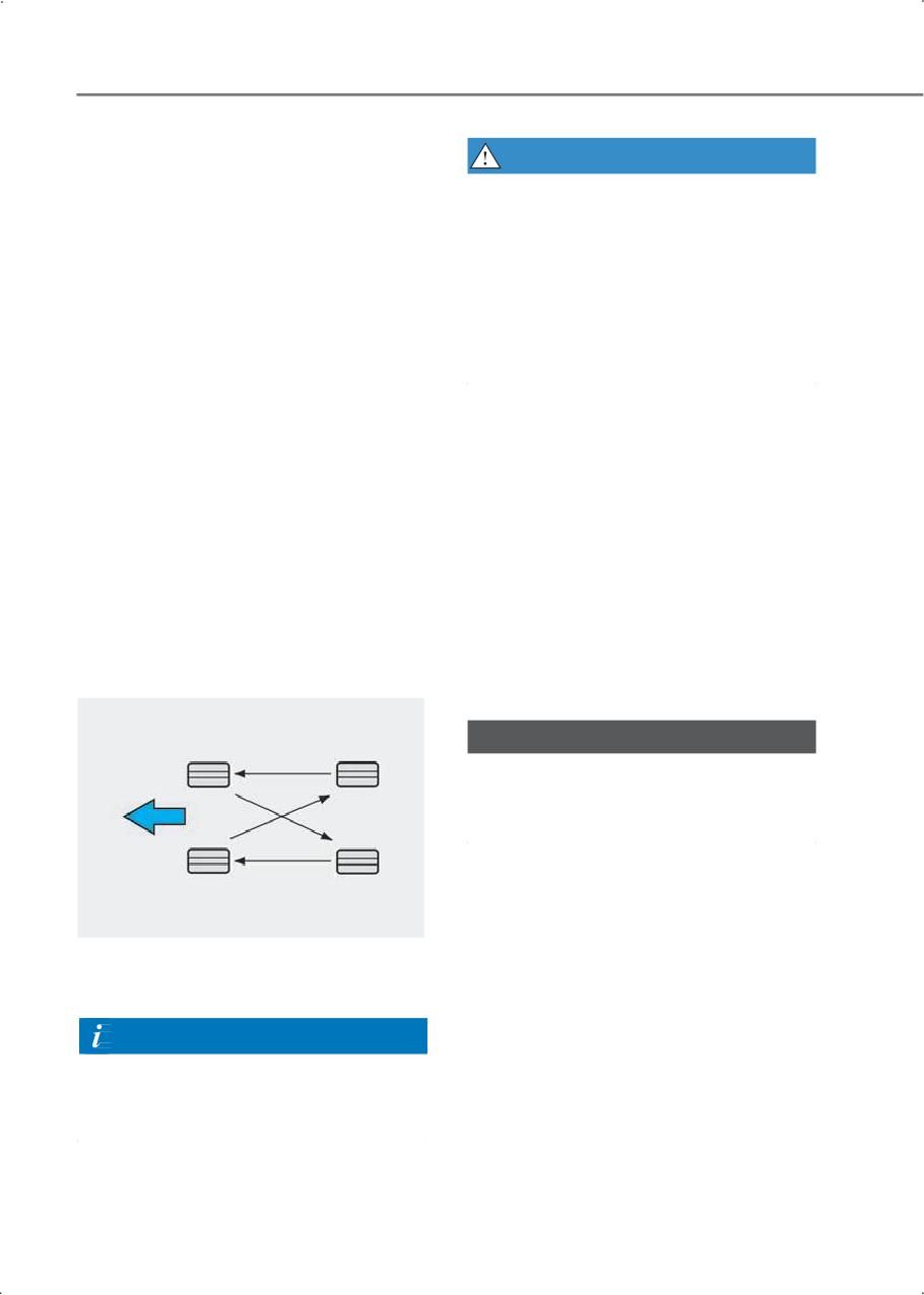
recommends that the tires be rotated
for tire rotation.
according to the maintenance
schedule or sooner if irregular wear
• Do not mix bias ply and radial ply
develops.
tires under any circumstances. This
may cause unusual handling
During rotation, check the tires for
characteristics that may cause loss
correct balance.
of vehicle control and result in a
When rotating tires, check for uneven
collision.
wear and damage. Abnormal wear is
usually caused by incorrect tire
pressure, improper wheel alignment,
Wheel alignment and tire
out-of-balance wheels, severe
balance
braking, or severe cornering. Look for
The wheels on your vehicle were
bumps or bulges in the tread or side
aligned and balanced carefully at the
of the tire. Replace the tire if you find
factory, and you may not need to
any of these conditions. Replace the
have your wheels aligned again. If
tire if fabric or cord is visible. After
you notice unusual tire wear or your
rotation, be sure to bring the front
vehicle pulling to one side, the
and rear tire pressures to
alignment may need to be adjusted.
specification and check wheel nut
torque (proper torque is 79.6-94.0
If you notice your vehicle vibrating
lbf.ft [11.0-13.0 kgf.m]).
when driving on a smooth road, your
wheels may need to be rebalanced.
NOTICE
Only use approved wheel weights or
your vehicle’s aluminum wheels may
be damaged.
Disc brake pads should be inspected
for wear whenever tires are rotated.
Information
When installing an unsymmetrical
tire, install the side marked "outside"
facing out.
9-18
9
Tire replacement
• When replacing tires (or wheels), it
is recommended to replace the two
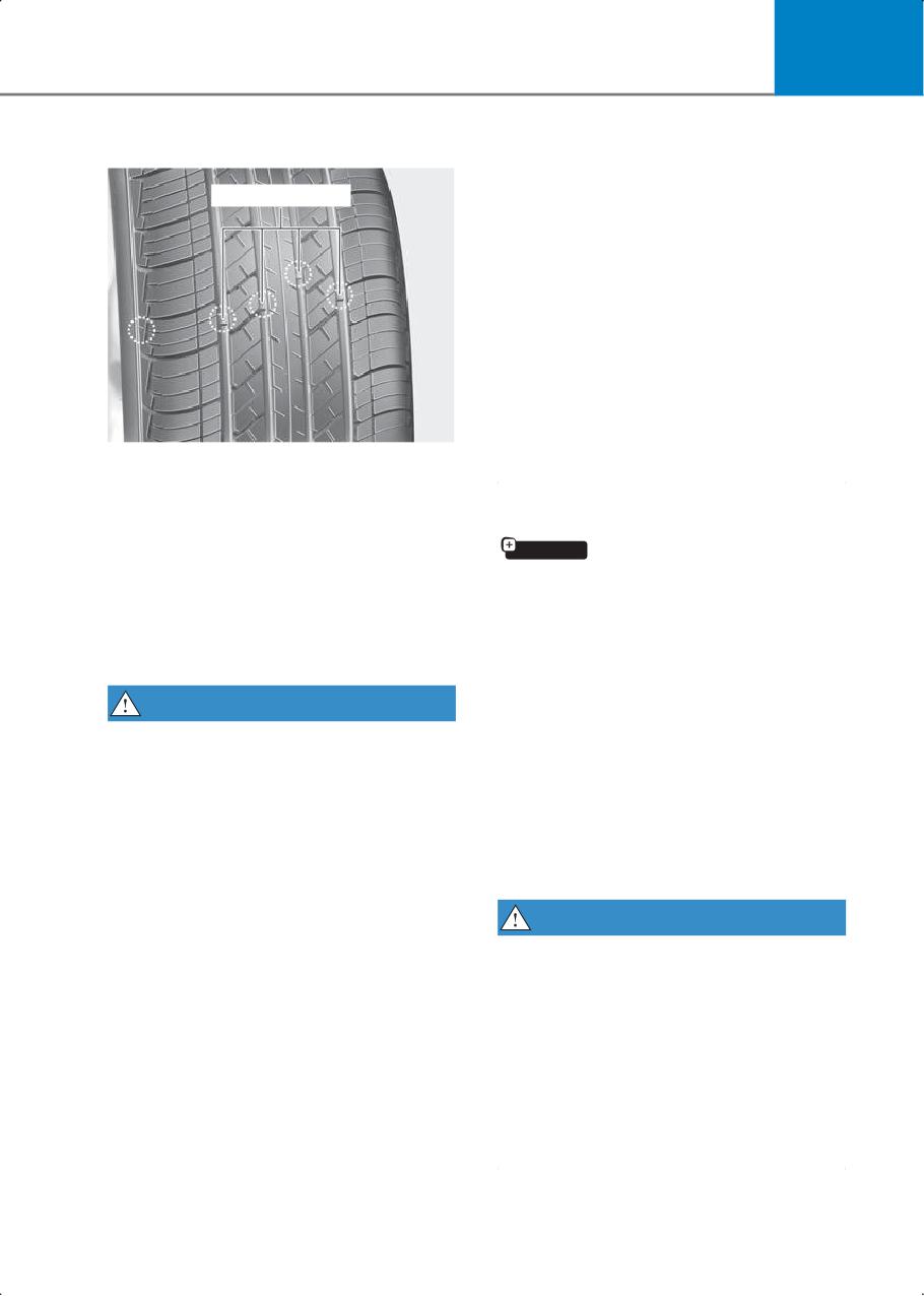
Tread wear indicator
front or two rear tires (or wheels) as
a pair. Replacing just one tire may
seriously affect your vehicle’s
handling.
• Tires degrade over time, even when
they are not being used. Regardless
of the remaining tread, HYUNDAI
recommends that tires be replaced
after six (6) years.
• Driving in hot climates or excessive
loading may accelerate the tire
aging process.
If the tire is worn evenly, a tread wear
indicator appears as a solid band
across the tread. This shows there is
Compact spare tire replacement
less than 1/16 in. (1.6 mm) of tread left
if equipped
on the tire. Replace the tire when this
A compact spare tire has a shorter
happens.
tread life than a regular size tire.
Do not wait for the band to appear
Replace it when you can see the tread
across the entire tread before
wear indicator bars on the tire. The
replacing the tire.
replacement compact spare tire
should be the same size and design
WARNING
tire as the one provided with your
To reduce the risk of serious injury or
vehicle and must be mounted on the
death:
same compact spare tire wheel. The
compact spare tire is not designed to
• Replace tires that are worn, show
be mounted on a regular size wheel,
uneven wear, or are damaged.
and the compact spare tire wheel is
Worn tires may cause loss of
not designed for mounting a regular
braking effectiveness, steering
size tire.
control, and traction.
• Always replace tires with the same
WARNING
size as each tire that was originally
The normal size tire should be
supplied with this vehicle. Using
repaired or replaced as soon as
tires and wheels other than the
possible to avoid failure of the spare
recommended sizes may cause
and loss of vehicle control resulting in
unusual handling characteristics,
a collision.
poor vehicle control, or negatively
affect your vehicle’s Anti-Lock
The compact spare tire is for
Brake System (ABS).
emergency use only. Do not operate
your vehicle over 50 mph (80 km/h)
when using the compact spare tire.
9-19
Maintenance
Wheel replacement
When replacing the metal wheels for
any reason, make sure the new
wheels are equivalent to the original
factory units in diameter, rim width,
and offset.
Tire traction
Tire traction can be reduced if you
drive on worn tires or the tires that
are improperly inflated, or on slippery
1. Manufacturer or brand name
road surfaces. Replace the tires when
Manufacturer or brand name is
tread wear indicators appear. To
shown.
reduce the possibility of losing
control, slow down whenever there is
rain, snow, or ice on the road.
2. Tire size designation
A tire’s sidewall is marked with a tire
size designation. You need this
Tire maintenance
information when selecting
In addition to proper inflation, correct
replacement tires for your vehicle.
wheel alignment helps decrease the
The following explains what the
tire wear. If you find a tire is worn
letters and numbers in the tire size
unevenly, have your dealer check the
designation mean.
wheel alignment. When you have
Example tire size designation:
new tires installed, make sure they
are balanced. This may increase ride
(These numbers are provided as an
comfort and tire life. Additionally, a
example only. Your tire size
tire must always be rebalanced if it is
designator may vary depending on
removed from the wheel.
your vehicle.)
205/55R16 91H
Tire sidewall labeling
205 - Tire width in millimeters.
This information identifies and
55 - Aspect ratio. The tire’s section
describes the fundamental
height as a percentage of its width.
characteristics of the tire and also
R - Tire construction code (Radial).
provides the tire identification
16 - Rim diameter in inches.
number (TIN) for safety standard
certification. The TIN can be used to
91 - Load Index, a numerical code
identify the tire in case of a recall.
associated with the maximum load
the tire can carry.
H - Speed Rating Symbol. See the
speed rating chart in this section for
additional information.
9-20
9
Wheel size designation
3. Checking tire life (TIN: Tire
Identification Number)
Wheels are also marked with
important information that you need
Any tires that are over six years old,
if you ever have to replace one.
based on the manufacturing date,
(including the spare tire) must be
Example wheel size designation:
replaced by new ones. You can find
6.5J X 16
the manufacturing date on the tire
6.5 - Rim width in inches.
sidewall (possibly on the inside of the
wheel), displaying the DOT Code. The
J - Rim contour designation.
DOT Code is a series of numbers on a
16 - Rim diameter in inches.
tire consisting of numbers and
English letters. The manufacturing
Tire speed ratings
date is designated by the last four
The chart below lists many of the
digits (characters) of the DOT code.
different speed ratings currently
being used for passenger vehicle
DOT: XXXX XXXX OOOO
tires. The speed rating is part of the
The front part of the DOT shows a
tire size designation on the sidewall
plant code number, tire size, and
of the tire. This symbol corresponds
tread pattern and the last four
to that tire’s designed maximum safe
numbers indicate the week and year
operating speed.
manufactured.
For example:
Speed Rating
Maximum Speed
DOT XXXX XXXX 1423 represents that
Symbol
the tire was produced in the 14th
S
112 mph (180 km/h)
week of 2023.
T
118 mph (190 km/h)
4. Tire ply composition and material
H
130 mph (210 km/h)
The number of layers or plies of
rubber-coated fabric in the tire. Tire
V
149 mph (240 km/h)
manufacturers also must indicate the
materials in the tire, which include
W
168 mph (270 km/h)
steel, nylon, polyester, and others.
Y
186 mph (300 km/h)
The letter "R" means radial ply
construction. The letter "D" means
diagonal or bias ply construction; and
the letter "B" means belted-bias ply
construction.
9-21
Maintenance
5. Maximum permissible inflation
Tread wear
pressure
The tread wear grade is a
This number is the greatest amount
comparative rating based on the
of air pressure that should be put in
wear rate of the tire when tested
the tire. Do not exceed the maximum
under controlled conditions on a
permissible inflation pressure. Refer
specified government test course.
to the Tire and Loading Information
For example, a tire graded 150 would
label for recommended inflation
wear one-and-a-half times (1½) as
pressure.
well on the government course as a
tire graded 100.
6. Maximum load rating
The relative performance of tires
This number indicates the maximum
depends upon the actual conditions
load in kilograms and pounds that
of their use, however, and may depart
can be carried by the tire. When
significantly from the norm due to
replacing the tires on the vehicle,
variations in driving habits, service
always use a tire that has the same
practices, and differences in road
load rating as the factory installed
characteristics and climate.
tire.
These grades are molded on the
sidewalls of passenger vehicle tires.
7. DOT Tire Quality Grading (U.S.
The tires available as standard or
Vehicles)
optional equipment on your vehicle
may vary depending on the grade.
The tires on your vehicle meet all U.S.
Federal Safety Requirements. All tires
Traction - AA, A, B & C
are also graded for treadwear,
The traction grades, from highest to
traction, and temperature
lowest, are AA, A, B, and C. Those
performance according to
grades represent the tire’s ability to
Department of Transportation (DOT)
stop on wet pavement as measured
standards.
under controlled conditions on
Uniform tire quality grading
specified government test surfaces
of asphalt and concrete. A tire
Quality grades can be found where
marked C may have poor traction
applicable on the tire sidewall
performance.
between tread shoulder and
maximum section width.
WARNING
For example:
The traction grade assigned to this
TREADWEAR 200
tire is based on straight ahead
TRACTION AA
braking traction tests, and does not
include acceleration, cornering,
TEMPERATURE A
hydroplaning, or peak traction
characteristics.
9-22
9
Temperature - A, B & C
Accessory weight
The temperature grades are A (the
This means the combined weight of
highest), B and C representing the
optional accessories. Some examples
tire’s resistance to the generation of
of optional accessories are automatic
heat and its ability to dissipate heat
transmission, power seats, and air
when tested under controlled
conditioning.
conditions on a specified indoor
laboratory test wheel.
Aspect ratio
Sustained high temperature may
The relationship of a tire’s height to
cause the material of the tire to
its width.
degenerate and reduce tire life, and
excessive temperature may lead to
Belt
sudden tire failure. The grade C
A rubber coated layer of cords that is
corresponds to a level of
located between the plies and the
performance that all passenger car
tread. Cords may be made from steel
tires must meet the Federal Motor
or other reinforcing materials.
Vehicle Safety Standard No. 109.
Grades A and B represent higher
levels of performance on the
Bead
laboratory test wheel than the
The tire bead contains steel wires
minimum required by law.
wrapped by steel cords that hold the
tire onto the rim.
WARNING
The temperature grade for this tire is
Bias ply tire
established for a tire that is properly
A pneumatic tire in which the plies
inflated and not overloaded.
are laid at alternate angles less than
Excessive speed, under-inflation,
90 degrees to the centerline of the
over-inflation, or excessive loading,
tread.
either separately or in combination,
may cause heat build-up and
possible sudden tire failure.
Cold tire pressure
The amount of air pressure in a tire,
measured in pounds per square inch
Tire terminology and
(psi) or kilopascals (kPa) before a tire
definitions
has built up heat from driving.
Air pressure
Curb weight
The amount of air inside the tire
This means the weight of a motor
pressing outward on the tire. Air
vehicle with standard and optional
pressure is expressed in pounds per
equipment including the maximum
square inch (psi) or kilopascal (kPa).
capacity of fuel, oil and coolant, but
without passengers and cargo.
9-23
Maintenance
DOT markings
Load index
A code molded into the sidewall of a
An assigned number ranging from 1 to
tire signifying that the tire is in
279 that corresponds to the load
compliance with the U.S. Department
carrying capacity of a tire.
of Transportation motor vehicle
safety standards. The DOT code
Maximum inflation pressure
includes the Tire Identification
The maximum air pressure to which a
Number (TIN), an alphanumeric
cold tire may be inflated. The
designator which can also identify
maximum air pressure is molded onto
the tire manufacturer, production
the sidewall.
plant, brand and date of production.
Maximum load rating
GVWR
The load rating for a tire at the
Gross Vehicle Weight Rating
maximum permissible inflation
pressure for that tire.
GAWR FRT
Gross Axle Weight Rating for the
Maximum loaded vehicle weight
Front Axle.
The sum of curb weight; accessory
weight; vehicle capacity weight; and
GAWRRR
production options weight.
Gross Axle Weight Rating for the Rear
axle.
Normal occupant weight
The number of occupants a vehicle is
Intended outboard sidewall
designed to seat multiplied by 150
The side of an asymmetrical tire, that
lbs. (68 kg).
must always face outward when
mounted on a vehicle.
Occupant distribution
Designated seating positions.
Kilopascal (kPa)
The metric unit for air pressure.
Outward facing sidewall
An asymmetrical tire has a particular
Light Truck (LT) tire
side that faces outward when
A tire designated by its manufacturer
mounted on a vehicle. The outward
as primarily intended for use on
facing sidewall bears white lettering
lightweight trucks or multipurpose
or bears manufacturer, brand, and/or
passenger vehicles.
model name molding that is higher or
deeper than the same moldings on
the inner facing sidewall.
Load ratings
The maximum load that a tire is rated
to carry for a given inflation pressure.
9-24
9
Passenger (P-Metric) tire
Sidewall
A tire used on passenger cars and
The portion of a tire between the
some light duty trucks and
tread and the bead.
multipurpose vehicles.
Speed rating
Ply
An alphanumeric code assigned to a
A layer of rubber-coated parallel
tire indicating the maximum speed at
cords.
which a tire can operate.
Pneumatic tire
Traction
A mechanical device made of rubber,
The friction between the tire and the
chemicals, fabric and steel or other
road surface. The amount of grip
materials, that, when mounted on an
provided.
automotive wheel provides the
traction and contains the gas or fluid
Tread
that sustains the load.
The portion of a tire that comes into
contact with the road.
Pneumatic options weight
The combined weight of installed
Treadwear indicators
regular production options weighing
Narrow bands, sometimes called
over 5 lb. (2.3 kg) in excess of the
"wear bars", that show across the
standard items which they replace,
tread of a tire when only 1/16 in. of
not previously considered in curb
tread remains.
weight or accessory weight,
including heavy duty breaks, ride
levelers, roof rack, heavy duty
UTQGS
battery, and special trim.
Uniform Tire Quality Grading
Standards is a tire information system
that provides consumers with ratings
Recommended inflation pressure
for a tire’s traction, temperature and
Vehicle manufacturer’s
treadwear. Ratings are determined
recommended tire inflation pressure
by tire manufacturers using
as shown on the tire placard.
government testing procedures. The
ratings are molded into the sidewall
Radial ply tire
of the tire.
A pneumatic tire in which the ply
cords that extend to the beads are
Vehicle capacity weight
laid at 90 degrees to the centerline of
The number of designated seating
the tread.
positions multiplied by 150 lbs. (68
kg) plus the rated cargo and luggage
Rim
load.
A metal support for a tire and upon
which the tire beads are seated.
9-25
Maintenance
Vehicle maximum load on the tire
California perchlorate
Load on an individual tire due to curb
notice
and accessory weight plus maximum
occupant and cargo weight.
Notice to California Vehicle Dismantlers:
The airbag module, safety belt
Vehicle normal load on the tire
pretensioners, and remote batteries must
be disposed of according to Title 22
Load on an individual tire that is
California Code of Regulations Section
determined by distributing to each
(a). Special handling may be
axle its share of the curb weight,
necessary. See:
accessory weight, and normal
occupant weight and dividing by 2.
e/perch lorate. Contact an
authorized HYUNDAI dealer for
handling and disposal.
Vehicle placard
A label permanently attached to a
vehicle showing the original
equipment tire size and
recommended inflation pressure.
9-26
10. Vehicle information,
reporting safety defects,
and consumer information
Vehicle Identification Number (VIN)
10-2
Vehicle certification label
10-2
Tire specification and pressure label
10-2
Engine number
10-3
Refrigerant label
10-3
Air conditioner compressor label
10-3
Operation in foreign countries
10-4
Hyundai vehicle owner privacy policy
10-5
Vehicle data collection and event data recorders
10-6
Reporting safety defects
10-7
FCC statement
Consumer information
10-9
Open source software notice
10-10
10
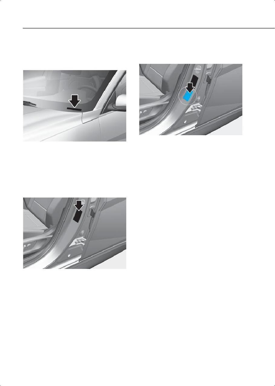
Vehicle information, reporting safety defects, and consumer information
Vehicle Identification
Tire specification and
Number (VIN)
pressure label
Vin label
The tires supplied on your new vehicle are
The VIN is also on a plate attached to the
chosen to provide the best performance
top of the left side dashboard. The
for normal driving.
number on the plate can easily be seen
The tire label located on the driver’s side
through the windshield from outside.
center pillar gives the tire pressures
recommended for your vehicle.
Vehicle certification label
The vehicle certification label attached on
the driver’s side center pillar gives the
vehicle identification number (VIN).
10-2
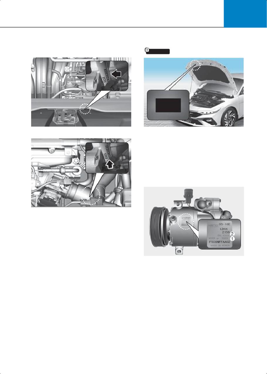
10
Engine number
Refrigerant label
if equipped
Smartstream G2.0 Atkinson
Smartstream G1.6 T-GDI
Therefrigerant label providesinformation
such as refrigerant type and amount.
(R-1234yf)
Air conditioner
compressor label
The engine number is stamped on the
engine block as shown in the drawing.
A compressor label informs you the type
of compressor your vehicle is equipped
with such as model, supplier part number,
production number, refrigerant (1) and
refrigerant oil (2).
10-3
Vehicle information, reporting safety defects, and consumer information
Operation in foreign countries
If you are going to drive your vehicle in another country, be sure to:
• Observe all regulations regarding registration and insurance.
• Determine that acceptable fuel is available.
10-4
10
Hyundai vehicle owner privacy policy
Your Hyundai vehicle may be equipped with technologies and services that use
information collected, generated, recorded, or stored by the vehicle. Hyundai has
created a Vehicle Owner Privacy Policy to explain how these technologies and services
collect use and share this information.
You may read our Vehicle Owner Privacy Policy on the Hyundaiusa.com website
If you would like to receive a hard copy of our Vehicle Owner Privacy Policy,
please contact our Customer Care Center at:
Hyundai Customer Care
P.O. Box 20850
Fountain Valley, CA 92728 800-633-5151
consumeraffairs@hmausa.com
Hyundai’s Customer Care representatives are available Monday through Friday, between
the hours of 6:00 AM and 5:00 PM PST and Saturday between 6:30 AM and 3:00 PM PST
(English).
For Customer Care assistance in Spanish or Korean, representatives are available
Monday through Friday between 6:30 AM and 3:00 PM PST.
10-5
Vehicle information, reporting safety defects, and consumer information
Vehicle data collection and event data recorders
This vehicle is equipped with an event data recorder (EDR). The main purpose of an EDR
is to record, in certain crash or near crash-like situations, such as an air bag deployment
or hitting a road obstacle, data that will assist in understanding how a vehicle’s systems
performed. The EDR is designed to record data related to vehicle dynamics and safety
systems for a short period of time, typically 30 seconds or less.
The EDR in this vehicle is designed to record such data as:
• How various systems in your vehicle were operating;
• Whether or not the driver and passenger safety belts were buckled/fastened;
• How far (if at all) the driver was depressing the accelerator and/or brake pedal; and,
• How fast the vehicle was traveling.
These data can help provide a better understanding of the circumstances in which
crashes and injuries occur.
NOTE: EDR data are recorded by your vehicle only if a non-trivial crash situation occurs;
no data are recorded by the EDR under normal driving conditions and no personal data
(for example, name, gender, age, and crash location) are recorded. However, other
parties, such as law enforcement, could combine the EDR data with the type of
personally identifying data routinely acquired during a crash investigation.
To read data recorded by an EDR, special equipment is required, and access to the
vehicle or the EDR is needed. In addition to the vehicle manufacturer, other parties, such
as law enforcement, that have the special equipment, can read the information if they
have access to the vehicle or the EDR.
10-6
10
Reporting safety defects
If you believe that your vehicle has a defect which could cause a crash or could
cause injury or death, you should immediately inform the National Highway
Traffic Safety Administration (NHTSA) in addition to notifying HYUNDAI MOTOR
AMERICA.
To contact NHTSA, you may call the Vehicle Safety Hotline toll-free at
1-888-327-4236 (TTY: 1-800-424-9153);
go to http://www.safercar.gov;
download the SaferCar mobile application;
or write to: Administrator, NHTSA1200 New Jersey Ave, SE,West Building
Washington, D.C. 20590.
You can also obtain other information about motor vehicle safety from
If NHTSA receives similar complaints, it may open an investigation, and if it finds
that a safety defect exists in a group of vehicles, it may order a recall and remedy
campaign. However, NHTSA cannot become involved in individual problems
between you, your dealer, or HYUNDAI MOTOR AMERICA.
10-7
Vehicle information, reporting safety defects, and consumer information
FCC statement
The following regulatory statement applies to all Radio Frequency (RF) devices
equipped in this vehicle:
This device complies with Part 15 of the FCC Rules and with Innovation, Science
and Economic Development Canada license-exempt RSS standard(s).
Operation is subject to the following two conditions:
1. This device may not cause harmful interference, and
2. This device must accept any interference received, including interference that
may cause undesired operation.
Le present appareil est conforme aux CNR d`Innovation, Science and
Economic Development applicables aux appareils radio exempts de
licence. L’exploitation est autorisee aux deux conditions suivantes:
1. l’appareil ne doit pas produire de brouillage, et
2. l’utilisateur de l’appareil doit accepter tout brouillage radioelectrique subi,
meme si le brouillage est susceptible d’en compromettre le fonctionnement.
La operacion de este equipo esta sujeta a las siguientes dos condiciones:
1. es posible que este equipo o dispositivo no cause interferencia perjudicial y
2. este equipo o dispositivo debe aceptar cualquier interferencia, incluyendo la
que pueda causar su operacion no deseada.
Information
Changes or modifications not expressly approved by the party responsible for
compliance could void the user’s authority to operate the equipment.
10-8
10
Consumer information
This consumer information has been prepared in accordance with regulations issued by
the National Highway Traffic Safety Administration of the U.S. Department of
Transportation. Your HYUNDAI dealer will help answer any questions you may have as
you read this information.
HYUNDAI motor vehicles are designed and manufactured to meet or exceed all
applicable safety standards.
For your safety, however, we strongly urge you to read and follow all directions in this
Owner’s Manual, particularly the information under the headings "NOTICE", "CAUTION",
and "WARNING".
If, after reading this manual, you have any questions regarding the operation of your
vehicle, please contact the Hyundai Customer Care Center:
Hyundai Customer Care
P.O. Box 20850
Fountain Valley, CA 92728
800-633-5151
consumeraffairs@hmausa.com
Hyundai’s Customer Care Center representatives are available Monday through Friday,
between the hours of 6:00 AM and 5:00 PM PST
and Saturday between 6:30 AM and 3:00 PM PST (English).
For Customer Care assistance in Spanish or Korean, representatives are available
Monday through Friday between 6:30 AM and 3:00 PM PST.
10-9
Vehicle information, reporting safety defects, and consumer information
Open source software notice
This vehicle contains software with open source licenses.
Open source software information including the source code, copyright notices and
referred license terms may be obtained on the website.
HYUNDAI Motor Company will provide the open source code to you in storage medium
such as CD-ROM for minimum charge covering the cost of performing source
distribution upon email request to opensource@hyundai.com within a period of 3 years
from the date of product purchase.
10-10
Index
I
Index
A
Accessing your vehicle
5-3
Remote key
5-3
Smart key
5-6
Air cleaner
9-9
Filter replacement
9-9
Air conditioner compressor label
10-3
Automatic climate control system
5-49
Automatic heating and air conditioning
5-50
Manual heating and air conditioning
5-51
B
Battery
9-12
Battery capacity label
9-14
Battery recharging
9-14
For longer battery life
9-13
Reset items
9-15
Before driving
6-2
Before entering the vehicle
6-2
Before starting
6-2
Vehicle break-in process
6-3
Before using driver assistance system
7-3
Driver assistance system settings
7-4
Blind-Spot Collision-Avoidance Assist (BCA)
7-37
Blind-Spot Collision-Avoidance Assist malfunction and limitations
7-41
Blind-Spot Collision-Avoidance Assist operation
7-39
Blind-Spot Collision-Avoidance Assist settings
7-38
Brake fluid
9-7
Checking the brake fluid level
9-7
Braking system
6-23
Anti-lock Brake System (ABS)
6-29
Auto Hold
6-27
Electronic Parking Brake (EPB)
6-25
Electronic Stability Control (ESC)
6-30
Parking brake
6-23
Power-assist brakes
6-23
C
California perchlorate notice
9-26
Center console overview
2-8
Child Restraint System (CRS)
3-27
Children always in the rear
3-27
Installing a Child Restraint System
3-30
Selecting a Child Restraint System
3-28
Consumer information
10-9
Convenience Features
5-1
Cruise Control (CC)
7-61
Cruise Control operation
7-61
I-2
I
D
Door locks
5-13
Child-protector rear door locks
5-15
Operating door locks from outside the vehicle
5-13
Operating door unlocks from inside the vehicle
5-13
Driver Assistance System
7-1
Driver assistance system sensors
7-102
Cameras
7-102
Radars
7-103
Ultrasonic sensors
7-104
Driver Attention Warning (DAW)
7-56
Driver Attention Warning malfunction and limitations
7-58
Driver Attention Warning operation
7-57
Driver Attention Warning settings
7-56
Driving Your Vehicle
6-1
Dual Clutch Transmission
6-17
Dual Clutch Transmission operation
6-18
Paddle shifter (Manual shift mode)
6-22
Parking
6-22
E
Emergency Situations
8-1
Engine Compartment
9-2
Engine compartment overview
2-10
Engine coolant
9-5
Changing coolant
9-7
Checking the coolant level
9-5
Engine number
10-3
Engine oil
9-3
Checking the engine oil and filter
9-4
Checking the engine oil level
9-3
Exterior lights
5-35
High beam operation
5-36
Lighting control
5-35
Turn signals and lane change signals
5-37
Exterior overview (Front view)
2-2
Exterior overview (Rear view)
2-4
F
Forward Collision-Avoidance Assist (FCA) (Front view camera only)
7-5
Forward Collision-Avoidance Assist malfunction and limitations
7-8
Forward Collision-Avoidance Assist operation
7-6
Forward Collision-Avoidance Assist settings
7-5
Forward Collision-Avoidance Assist (FCA) (Sensor fusion)
7-16
Forward Collision-Avoidance Assist malfunction and limitations
7-24
Forward Collision-Avoidance Assist operation
7-18
Forward Collision-Avoidance Assist settings
7-17
Fuel filler door
5-33
Closing the fuel filler door
5-33
I-3
Index
Opening the fuel filler door
5-33
H
Hazard warning flasher
8-2
High Beam Assist (HBA)
5-39
High Beam Assist malfunction and limitations
5-41
High Beam Assist operation
5-40
High Beam Assist settings
5-40
Highway Driving Assist (HDA)
7-87
Highway Driving Assist malfunction and limitations
7-90
Highway Driving Assist operation
7-88
Highway Driving Assist settings
7-87
Hood
5-27
Closing the hood
5-28
Opening the hood
5-27
HYUNDAI Motor America
1-3
Hyundai vehicle owner privacy policy
10-5
I
If you have a flat tire (with spare tire)
8-9
Changing tires
8-12
Jack and tools
8-9
Jack label
8-11
If you have a flat tire (with Tire Mobility Kit)
8-16
Components of the Tire Mobility Kit
8-17
How to adjust tire pressure
8-21
Introduction
8-16
Notes on the safe use of the Tire Mobility Kit
8-17
Using the Tire Mobility Kit When a tire is flat
8-18
Important safety precautions
3-3
Airbag hazards
3-3
Always wear your seat belt
3-3
Control your speed
3-4
Driver distraction
3-3
Keep your vehicle in proper operating condition - Inspecting your tires
3-4
Never drink or take drugs and drive
3-4
Restrain all children
3-3
Index
11-1
Infotainment system
5-60
How vehicle radio works
5-61
Steering wheel audio control
5-60
Instrument Cluster
4-1
Instrument cluster
4-2
Warning and indicator lights
4-3
Intelligent Speed Limit Assist (ISLA)
7-51
Intelligent Speed Limit Assist malfunction and limitations
7-54
Intelligent Speed Limit Assist operation
7-52
Intelligent Speed Limit Assist settings
7-52
Intelligent Variable Transmission (IVT)
6-12
I-4
I
Intelligent Variable Transmission operation
6-13
Parking
6-16
Interior lights
5-38
Interior lights auto off
5-38
Interior overview
2-6
Introduction
1-1,
1-2
J
Jump starting
8-2
K
Key ignition switch
6-3
Key ignition switch positions
6-5
Starting the engine
6-6
Turning off the engine
6-6
L
Lane Following Assist (LFA)
7-84
Lane Following Assist malfunction and limitations
7-86
Lane Following Assist operation
7-84
Lane Keeping Assist (LKA)
7-32
Lane Keeping Assist malfunction and limitations
7-35
Lane Keeping Assist operation
7-33
Lane Keeping Assist settings
7-32
M
Maintenance
9-1
Manual climate control system
5-44
Heating and air conditioning
5-45
Manual Speed Limit Assist (MSLA)
7-49
Manual Speed Limit Assist operation
7-49
Mirrors
5-18
Inside rearview mirror
5-18
Side view mirrors
5-19
N
Navigation-based Smart Cruise Control (NSCC)
7-79
Limitations of Navigation-based Smart Cruise Control
7-81
Navigation-based Smart Cruise Control operation
7-80
Navigation-based Smart Cruise Control settings
7-79
O
Open source software notice
10-10
Operation in foreign countries
10-4
P
Parking brake
9-8
I-5
Index
Checking the parking brake
9-8
Picture Index
2-1
Push button start ignition switch
6-7
Push button start ignition switch positions
6-8
Starting the engine
6-9
Turning off the engine
6-10
R
Rear Cross-Traffic Collision-Avoidance Assist (RCCA)
7-94
Rear Cross-Traffic Collision-Avoidance Assist malfunction and limitations
7-98
Rear Cross-Traffic Collision-Avoidance Assist operation
7-95
Rear Cross-Traffic Collision-Avoidance Assist settings
7-94
Rear Occupant Alert (ROA)
5-16
System operations
5-16
System setting
5-16
Rear View Monitor (RVM)
7-91
Rear View Monitor malfunction and limitations
7-93
Rear View Monitor operation
7-92
Rear View Monitor settings
7-92
Refrigerant label
10-3
Reporting safety defects
10-7
FCC statement
10-8
S
Safe Exit Warning (SEW)
7-45
Safe Exit Warning malfunction and limitations
7-47
Safe Exit Warning operation
7-46
Safe Exit Warning settings
7-45
Safety messages
1-4
Seat belts
3-18
Additional seat belt safety precautions
3-25
Care of seat belts
3-27
Seat belt restraint system
3-20
Seat belt safety precautions
3-18
Seat belt warning light
3-19
Seats
3-5
Front seats
3-7
Head restraints
3-13
Rear seats
3-11
Safety precautions
3-6
Seat warmers
3-17
Seats & Safety System
3-1
Smart Cruise Control (SCC)
7-64
Smart Cruise Control malfunction and limitations
7-73
Smart Cruise Control operation
7-65
Smart Cruise Control settings
7-65
Steering wheel
5-17
Motor Driven Power Steering (MDPS)
5-17
Tilt/telescopic steering
5-17
I-6
I
Sunroof
5-24
Automatic reversal
5-26
Slide open/close
5-26
Sunshade
5-25
Tilt open/close
5-25
Supplemental restraint system - airbags
3-36
Additional safety precautions
3-56
Airbag warning labels
3-56
How does the airbag system operate?
3-42
Occupant Classification System (OCS)
3-46
SRS care
3-55
SRS components
3-38
SRS warning light
3-45
What to expect after an airbag inflates
3-44
Where are the airbags?
3-39
Why didn’t my airbag go off in a collision?
3-51
T
Tire Pressure Monitoring System (TPMS)
8-4
Changing a tire with TPMS
8-8
Check tire pressure
8-5
Low tire pressure position and tire pressure telltale
8-6
Low tire pressure warning light
8-6
Tire pressure monitoring system
8-5
TPMS malfunction indicator
8-7
Tire specification and pressure label
10-2
Tires and wheels
9-16
Check tire inflation pressure
9-17
Recommended cold tire inflation pressures
9-16
Tire care
9-16
Tire maintenance
9-20
Tire replacement
9-19
Tire rotation
9-18
Tire sidewall labeling
9-20
Tire terminology and definitions
9-23
Tire traction
9-20
Wheel alignment and tire balance
9-18
Wheel replacement
9-20
Trailer towing
6-34
Trunk
5-29
Emergency trunk safety release
5-29
Smart Trunk release
5-30
V
Vehicle Auto-Shut Off
6-10
Deactivating conditions
6-11
Operating conditions
6-10
System operation
6-11
Vehicle break-in process
1-6
I-7
Index
Vehicle certification label
10-2
Vehicle data collection and event data recorders
10-6
Vehicle Identification Number (VIN)
10-2
Vehicle Information, Reporting Safety Defects, and Consumer Information
10-1
Vehicle load limit
6-35
The loading information label
6-35
Vehicle modifications
1-5
Vehicle settings (infotainment system)
4-14
Setting your vehicle
4-14
W
Washer fluid
9-9
Checking the washer fluid level
9-9
Windows
5-21
Power windows
5-22
Windshield defrosting and defogging
5-55
Auto defogging system (only for automatic climate control system)
5-59
Automatic climate control system
5-57
Defogging logic
5-57
Manual climate control system
5-56
Rear window defroster
5-58
Winter driving
6-33
Snow or icy conditions
6-33
Wiper blades
9-11
Blade inspection
9-11
Blade replacement
9-11
Wipers and washers
5-42
Front windshield washers
5-43
Windshield wipers
5-42
I-8