Hyundai Santa Fe (2006 year). Manual - part 789
REAR SUSPENSION SYSTEM
SS -63
INSTALLATION
EC498CBE
1.
Install the rear trailing arm (A) to the rear carrier.
Tightening torque Nm (kgf-m, lb-ft) :
Bolt(B) : 137.3~156.9 (14~16, 101.3~115.7)
Nut(C) : 137.3~156.9 (14~16, 101.3~115.7)
A
C
B
SCMSS6039D
NOTE
After checking the distance(453±10mm(17.83
±0.39in)) between the wheel housing garnish (A) and
the hub assembly (B) as shown in the illustration,
tighten the mounting bolts and nuts of rear chassis
part with specified torque.
A
B
453 10 mm
SCMSS6528D
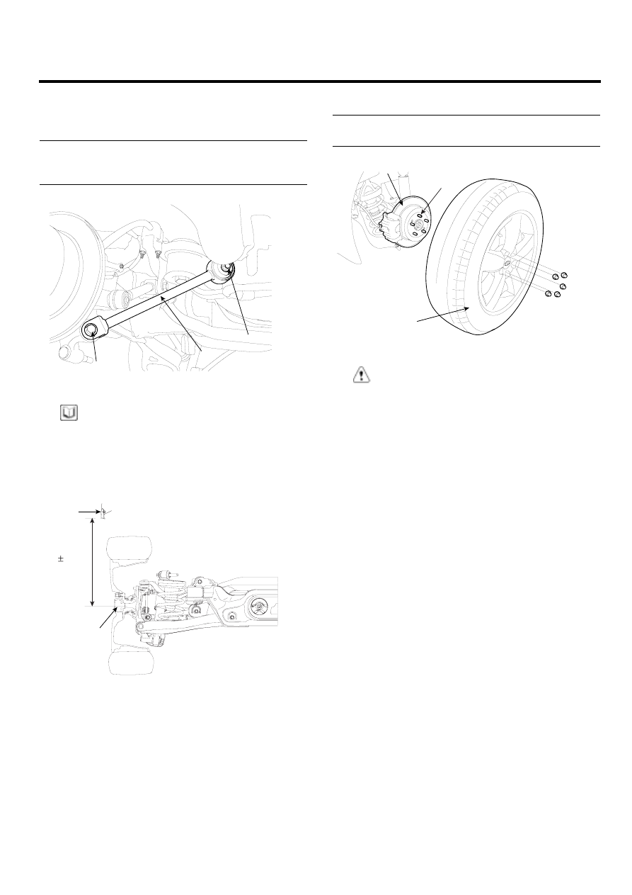
2.
Install the wheel and tire (A) to the rear hub (B).
Tightening torque Nm (kgf-m, lb-ft) :
88.3~107.9 (9~11, 65.1~79.6)
A
B
C
SCMSS6512D
CAUTION
Be careful not to damage the hub bolts (C) when
installing the rear wheel and tire (A).