Hyundai Santa Fe (2006 year). Manual - part 787
REAR SUSPENSION SYSTEM
SS -55
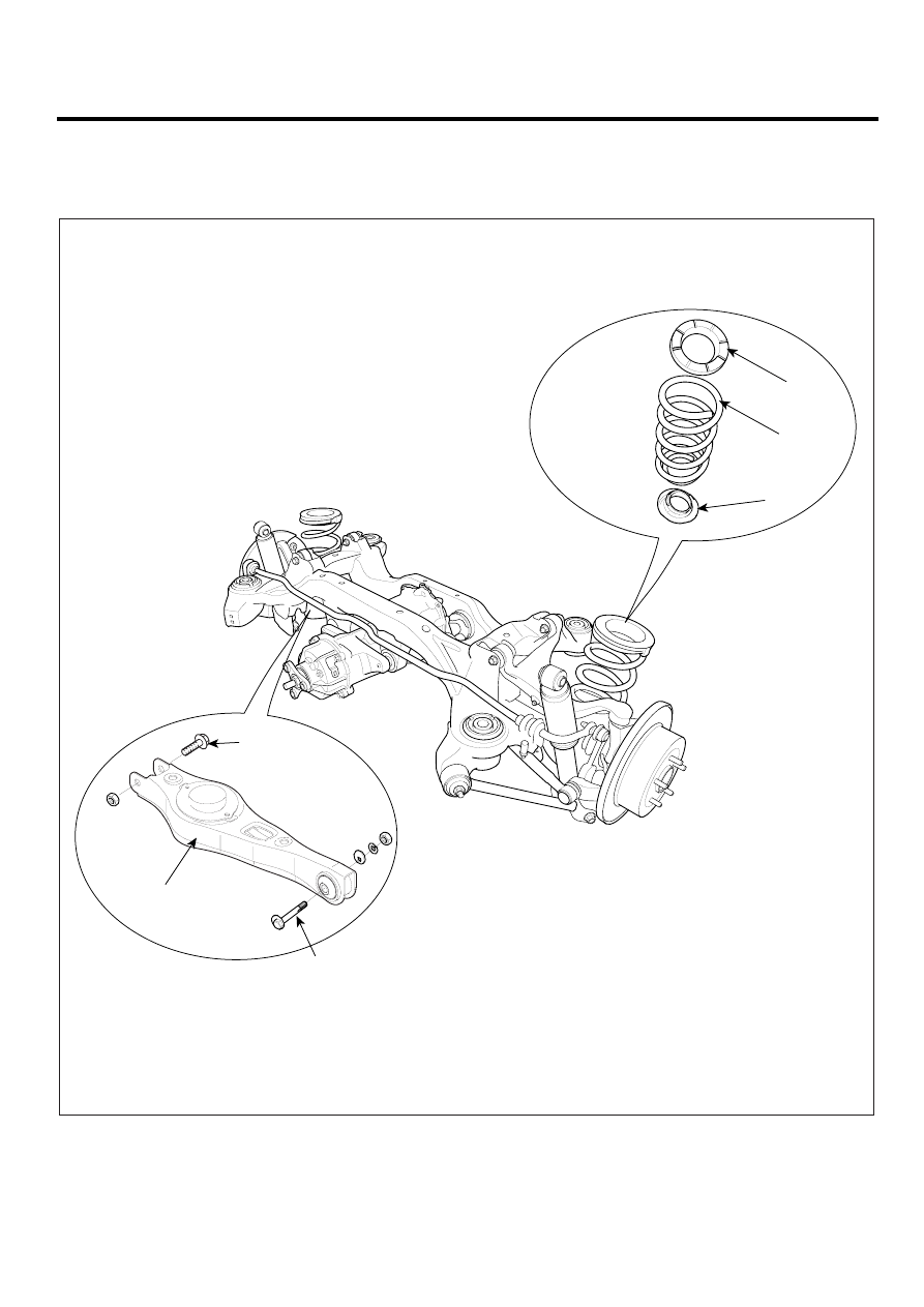
REAR LOWER ARM
COMPONENT
EBAFBDF9
1. Rear lower arm
2. Rear coil spring upper pad
3. Rear coil spring
4. Rear coil spring lower pad
TORQUE : Nm (kgf.m, lb-ft)
137.3~156.9
(14~16, 101.3~115.7)
137.3~156.9
(14~16, 101.3~115.7)
1
2
3
4
SCMSS6507L