Hyundai Santa Fe (2006 year). Manual - part 733


  Index      Hyundai     Hyundai Santa Fe - service repair manual 2006 year


Search            


Content   ..  731  732  733  734   ..


Hyundai Santa Fe (2006 year). Manual - part 733


MT -92

MANUAL TRANSAXLE (M5GF2)

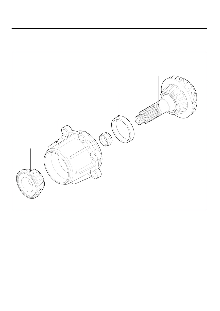
PINION SHAFT AND CASE

COMPONENTS

E3FABF07

3

2

4

1

1.  Pinion shaft
2.  Pinion case

3.  Taper roller bearing
4.  Taper roller bearing outer race

UMQG005A

TRANSFER CASE ASSEMBLY

MT -93

DISASSEMBLY

E4671E56

1.

Remove the O-ring(A) from the pinion shaft and case
assembly.

A

UMQG005B

2.

Remove the spacer(A).

A

UMQG005C

3.

Loosen the HEX lock nut(A).

A

SCMMT6080D

4.

Remove the rear flange assembly(A).

A

SCMMT6081D

5.

Using the SST(09455-32200), remove the oil seal(A)
from the pinion case.

09455-32200

A

UMQG005F

6.

Using a press machine, remove the pinion shaft(A)
from the pinion case(B).

A

B

UMQG005G

MT -94

MANUAL TRANSAXLE (M5GF2)

7.

Take out the taper roller bearing(A) from the pinion
case(B).

A

B

UMQG005H

8.

Using a sliding hammer(A), remove the taper roller
bearing outer race(B) from the pinion case(C).

A

B

C

UMQG005I

REASSEMBLY

E546DB0B

1.

Assemble the taper roller bearing outer races.

2.

Using a press machine, install the taper roller bear-
ing(C) and the pinion shaft(A) in the pinion case(B).

A

B

UMQG005J

C

UMQG005K

3.

Install the oil seal and the rear flange assembly as
shown below and screw down the hex lock nut(A) until
an axial clearance B of 0.25mm to 0.75mm between
pinion and pinion case results.

A

SCMMT6080D

TRANSFER CASE ASSEMBLY

MT -95

1)

Measurement of B

• Apply an additional 200N tension load F1 to

the pinion head according to arrangement
Y. Rotate the pinion 10 times and measure
dimension C.

• Apply a 200N load F2 to the rear flange. Ro-

tate the pinion 10 times and measure dimen-
sion D.
B=C-D

F1

F2

Ev (A

T FORCE F2)

D (A

T FORCE F2)

C (A

T FORCE F1)

En (AFTER 

TIGHTENING OF HEX LOCK NUT)

UMQG005L

2)

Measure dimension Ev.

3)

Tighten HEX lock nut.

4)

Measure the drag torque of the pinion assem-
bly. Target is 180-210Ncm. To achieve the tar-
get preload torque, it is permissible to gradually
increase the tightening torque.

CAUTION

If the permissible preload torque of 210Ncm is ex-
ceeded, it is not allowed to loosen Hex lock nut.
Disassemble the whole pinion assembly. Replace
the collapsible spacer and repeat the mounting
procedure.

5)

Measure dimension En.

6)

Check preload. A preload torque of 180 to 210
Ncm corresponds to a bearing preload of 0.12 to
0.16mm.
Ev-En-B=0.12 to 0.16mm

CAUTION

Twice use of collapsible spacer is not permit-
ted(Permanent deformation).

4.

Assemble the O-ring and select the proper spacer
later when reassembling the transfer case.


Content   ..  731  732  733  734   ..